


Section 21 IEBus
TM
Controller
Page 1098 of 2108 R01UH0134EJ0400 Rev. 4.00
Sep 24, 2014
SH7262 Group, SH7264 Group
(2) Data Command Transfer (Control Bits: Read (H'3, H'7), Write (H'A, H'B, H'E, H'F))
In the case of data read (H'3, H'7), data in the data buffer of the slave unit is read in the master
unit. In the case of data write (H'B or H'F) or command write (H'A or H'E), data received in the
slave unit is processed in accordance with the operation specification of the slave unit.
Notes: 1. The user can select data and commands freely in accordance with the system.
2. H'3, H'A, or H'B may lock depending on the communications condition and status.
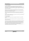
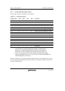
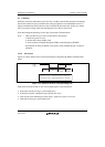
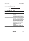
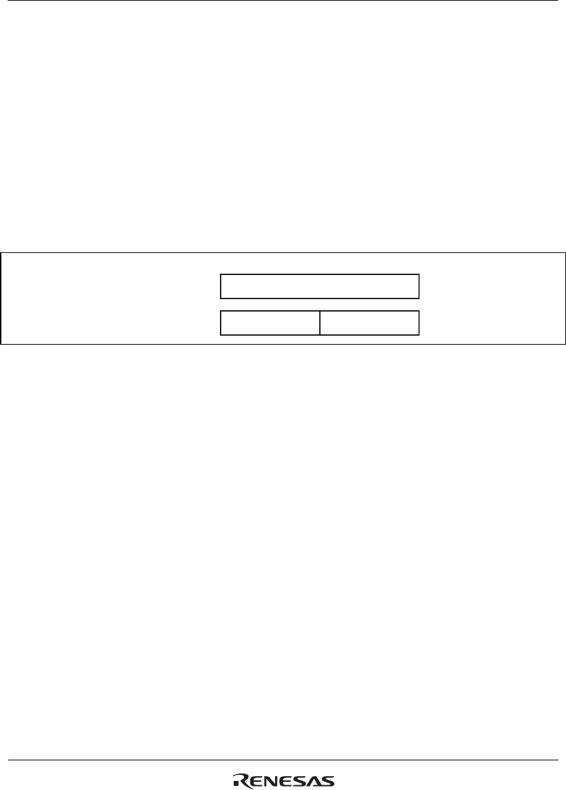
(3) Locked Address Read (Control Bits: H'4, H'5)
In the case of the locked address read (H'4 or H'5), the address (12 bits) of the master unit, which
issues the lock instruction, is configured in bytes as shown in figure 21.3.
MSB
Lower 8 bits
Undefined
Control bits: H'4
Control bits: H'5 Upper 4 bits
LSB
Figure 21.3 Locked Address Configuration
(4) Locking/Unlocking (Control Bits: Setting (H'3, H'A, H'B), Cancellation: (H'6))
The lock function is used for message transfer over multiple communications frames. A locked
unit receives data only from the unit which locked it.
Locking and unlocking are described below.
(a) Locking
When an acknowledge bit of 0 in the message length field is transmitted/received with the control
bits (H'3, H'A, H'B) indicating the lock operation, and then the communications frame is
completed before completion of data transmission/reception for the number of bytes specified by
the message length bits, the slave unit is locked by the master unit. In this case, the bit (bit 2)
relevant to locking in the byte data indicating the slave status is set to 1.
Lock is set only when the number of data exceeds the maximum number of transfer bytes in one
frame. Lock is not set by other error terminations.