


Section 22 Renesas SPDIF Interface
R01UH0134EJ0400 Rev. 4.00 Page 1185 of 2108
Sep 24, 2014
SH7262 Group, SH7264 Group
22.9 Functional Description—Receiver
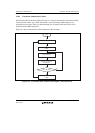
22.9.1 Receiver Module
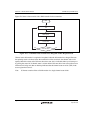
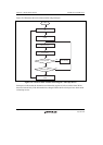
The receiver module demodulates data and clock signals from the input encoded according to the
IEC60958 standard. The encoded data, shown in linear PCM format, is stored into the audio data
register. The register also stores the channel status and user information being received
simultaneously as auxiliary information.
The main clock for the receiver module is an oversampling clock supplied from the outside. The
module operates at a frequency four times as large as the oversampling clock.
Note: The oversampling clock is the same for the transmitter and receiver.
Clock recovery is performed using a pulse width counter and averaging filters to produce a
sampling pulse in the middle of each bit in the datastream. A clock error status bit indicates clock
synchronization loss. Synchronization is achieved when a preamble occurs on the data stream for
the first time. Continuous adjustment prevents jitter and/or clock drift from affecting clock
recovery, provided that they fall within the clock recovery specifications.
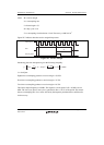
Once the clock recovery is successful the biphase-mark decoder initiates its preamble detection.
The decoder searches for the start of block preamble (see table 22.2). A preamble error status bit
indicates that following preambles have not appeared at the correct time, such failures are most
likely caused by transmission loss or interference.
Even parity checking is performed on the decoded data. A discrepancy will result in the parity
error status bit being set.
The SPDIF module acquires user data and channel status information in addition to audio data.
The audio is stored in a double buffer arrangement. Either an interrupt request because of a full
buffer or polling of the status bit will indicate when the data is ready to be read. DMA transfers
receive channel 1 audio data on the first request and channel 2 data on the second.
Channel status is stored in a 30-bit register. Channel status information is received at 1-bit per
subframe. Therefore the registers will not be full until a total of 30 frames for each channel have
been received. New channel status is compared with the current data to see if it has changed and is
only read by the processor if it has. User data, which is also received at the same time, is stored
into the register on a subframe basis, so that the reception is completed when 16 frames are
reached.