


Section 2 CPU
Page 74 of 2108 R01UH0134EJ0400 Rev. 4.00
Sep 24, 2014
SH7262 Group, SH7264 Group
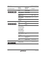
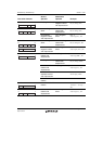
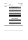
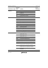
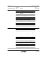
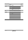
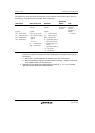
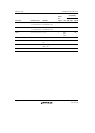
The table below shows the format of instruction codes, operation, and execution states. They are
described by using this format according to their classification.
Instruction Instruction Code Operation
Execution
States T Bit
Indicated by mnemonic.
[Legend]
Rm: Source register
Rn: Destination register
imm: Immediate data
disp: Displacement*
2
Indicated in MSB
LSB order.
[Legend]
mmmm: Source register
nnnn: Destination register
0000: R0
0001: R1
.........
1111: R15
iiii: Immediate data
dddd: Displacement
Indicates summary of
operation.
[Legend]
, : Transfer direction
(xx): Memory operand
M/Q/T: Flag bits in SR
&: Logical AND of each bit
|: Logical OR of each bit
^: Exclusive logical OR of
each bit
~: Logical NOT of each bit
<<n: n-bit left shift
>>n: n-bit right shift
Value when no
wait states are
inserted.
*
1
Value of T bit after
instruction is
executed.
Explanation of
Symbols
: No change
Notes: 1. Instruction execution cycles: The execution cycles shown in the table are minimums. In
practice, the number of instruction execution states will be increased in cases such as
the following:
a. When there is a conflict between an instruction fetch and a data access
b. When the destination register of a load instruction (memory register) is the same
as the register used by the next instruction.
2. Depending on the operand size, displacement is scaled by 1, 2, or 4. For details,
refer to the SH-2A, SH2A-FPU Software Manual.