


Section 21 IEBus
TM
Controller
R01UH0134EJ0400 Rev. 4.00 Page 1097 of 2108
Sep 24, 2014
SH7262 Group, SH7264 Group
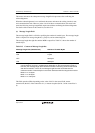
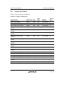
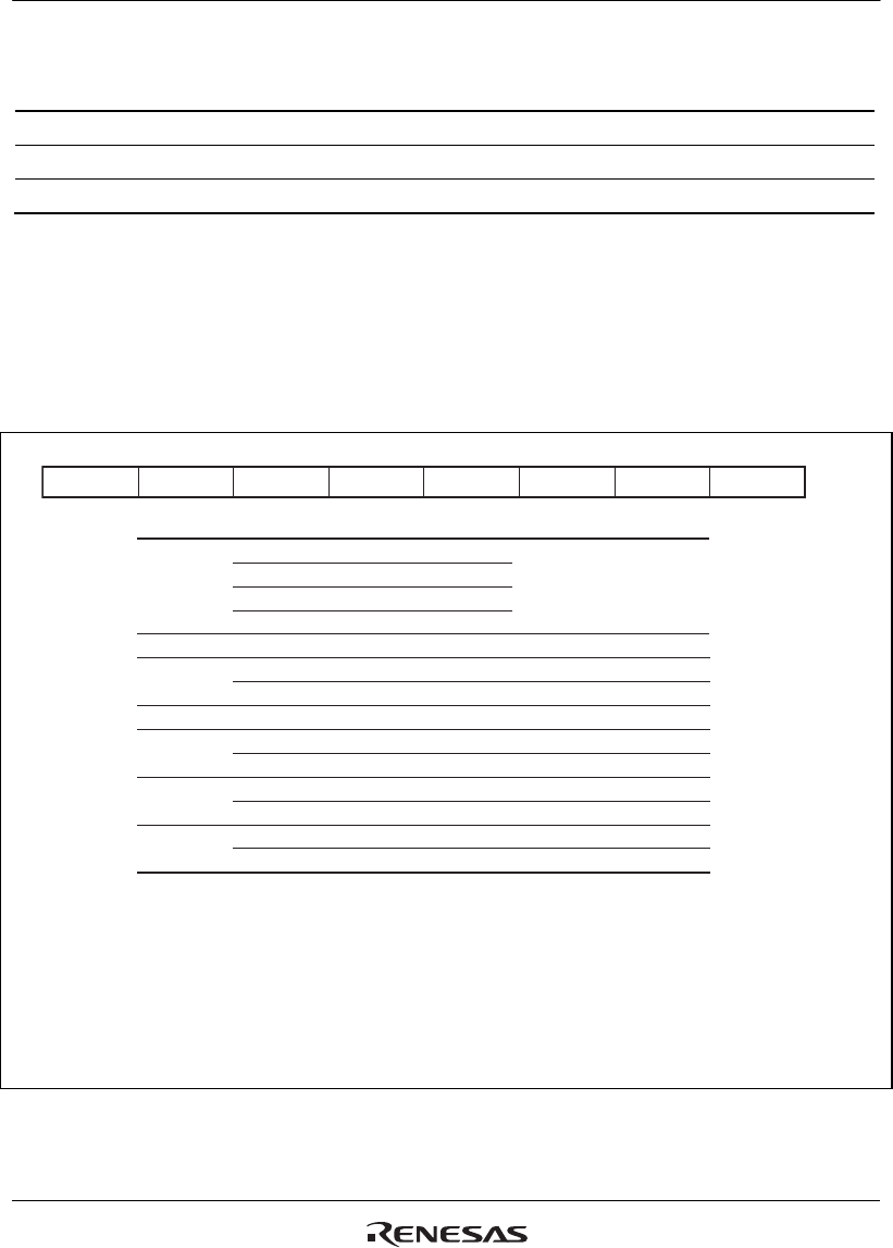
Table 21.5 Control Field for Locked Slave Unit
Setting Value Bit 3 Bit 2 Bit 1 Bit 0 Function
H'0 0 0 0 0 Reads slave status
H'4 0 1 0 0 Reads locked address (upper 8 bits)
H'5 0 1 0 1 Reads locked address (lower 4 bits)
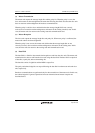
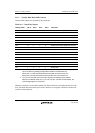
(1) Slave Status Read (Control Bits: H'0, H'6)
The master unit can decide the reason the slave unit does not return the acknowledgement (ACK)
by reading the slave status (H'0, H'6). The slave status indicates the result of the last
communications that the slave unit performed. All slave units can provide slave status
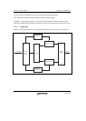
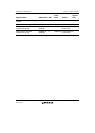
information. Figure 21.2 shows the bit configuration of the slave status.
MSB
Bit 7
Notes: 1. Since this LSI can support up to mode 2, bits 6 and 7 are fixed to 10.
2. The value of bit 4 can be selected by the STE bit in the IEBus master unit address register 1 (IEAR1).
3. The slave receive buffer is a buffer which is accessed during data write
(control bits: H'A, H'B, H'E, H'F).
In this LSI, the slave receive buffer corresponds to the IEBus receive buffer register (IERB001 to IERB128);
and bit 1 is the value of the RXBSY bit in the IEBus receive status register (IERSR).
4. The slave transmit buffer is a buffer which is accessed during data read
(control bits: H'3, H'7).
In this LSI, the slave transmit buffer corresponds to the IEBus transmit buffer register
(IETB001 to IETB128) and bit 0 is the value of the SRQ bit in the IEBus general flag registers (IEFLG).
Bit 7, bit 6
Bit 5
Bit 3
Bit 2
Bit 4*
2
Bit 1*
3
Bit 0*
4
00
01
10
11
Mode 0 Indicates the highest mode
supported by a unit. *
1
Mode 1
Mode 2
For future use
Fixed 0
Fixed 0
Slave transmission halted
Slave transmission enabled
Slave receive buffer is empty
Slave receive buffer is not empty
Slave transmit buffer is empty
Slave transmit buffer is not empty
Unit is unlocked
Unit is locked
0
0
0
0
1
1
1
1
0
0
Bit Value Description
Bit 6 Bit 5 Bit 4 Bit 3 Bit 2 Bit 1 Bit 0
LSB
Figure 21.2 Bit Configuration of Slave Status (SSR)