


Section 26 USB 2.0 Host/Function Module
R01UH0134EJ0400 Rev. 4.00 Page 1493 of 2108
Sep 24, 2014
SH7262 Group, SH7264 Group
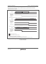
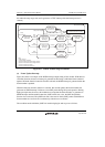
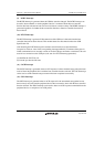
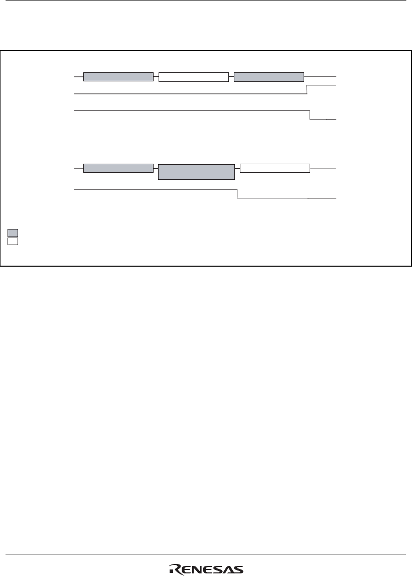
Figure 26.5 shows the timing at which a BEMP interrupt is generated when the function controller
function has been selected.
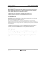
(*1
IN Token Packet
OUT Token Packet
ACK Handshake Data Packet
STALL Handshake
Data Packet (Maximum
p
acket size over
)
*1 In isochronous transfer, Handshake is not transmitted.
(1) Data transmission
USB bus
Buffer memory status
Transmission enabled state
Writing enabled state
(there is no data to be transmitted)
BRDY interrupt
(corresponding
PIPEBEMP bit is
changed)
(2) Data reception
USB bus
BRDY interrupt
(corresponding
PIPEBEMP bit is
changed)
Packet transmitted by the host
Packet transmitted by the peripheral module
*1
Figure 26.5 Timing at which BEMP Interrupt is Generated when Function Controller
Function is Selected
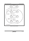
(4) Device State Transition Interrupt
Figure 26.6 shows a diagram of this module device state transitions. This module controls device
states and generates device state transition interrupts. However, recovery from the suspended state
(resume signal detection) is detected by means of the resume interrupt. The device state transition
interrupts can be enabled or disabled individually using INTENB0. The device state that made a
transition can be confirmed using the DVSQ bit in INTSTS0.
To make a transition to the default state, the device state transition interrupt is generated after the
reset handshake protocol has been completed.
Device state can be controlled only when the function controller function is selected. Also, the
device state transition interrupts can be generated only when the function controller function is
selected.