


Section 11 Multi-Function Timer Pulse Unit 2
Page 520 of 2108 R01UH0134EJ0400 Rev. 4.00
Sep 24, 2014
SH7262 Group, SH7264 Group
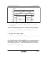
For input capture in cascade connection, refer to section 11.7.22, Simultaneous Capture of
TCNT_1 and TCNT_2 in Cascade Connection.
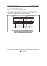
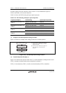
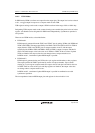
Table 11.43 show the TICCR setting and input capture input pins.
Table 11.43 TICCR Setting and Input Capture Input Pins
Target Input Capture TICCR Setting Input Capture Input Pins
Input capture from TCNT_1 to
TGRA_1
I2AE bit = 0 (initial value) TIOC1A
I2AE bit = 1 TIOC1A, TIOC2A
Input capture from TCNT_1 to
TGRB_1
I2BE bit = 0 (initial value) TIOC1B
I2BE bit = 1 TIOC1B, TIOC2B
Input capture from TCNT_2 to
TGRA_2
I1AE bit = 0 (initial value) TIOC2A
I1AE bit = 1 TIOC2A, TIOC1A
Input capture from TCNT_2 to
TGRB_2
I1BE bit = 0 (initial value) TIOC2B
I1BE bit = 1 TIOC2B, TIOC1B
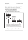
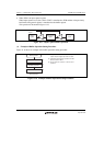
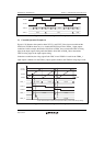
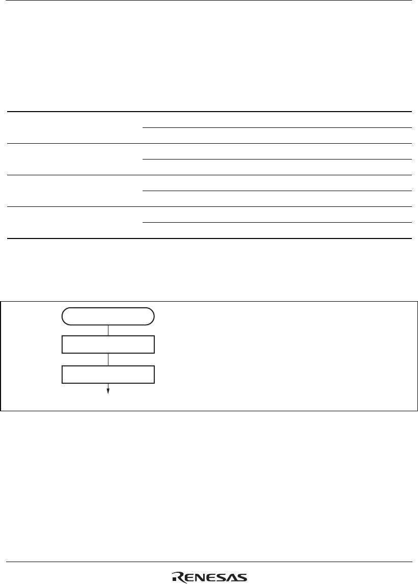
(1) Example of Cascaded Operation Setting Procedure
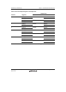
Figure 11.20 shows an example of the setting procedure for cascaded operation.
Cascaded operation
Set cascading
Start count
<Cascaded operation>
[1]
[2]
[1] Set bits TPSC2 to TPSC0 in the channel 1
TCR to B'111 to select TCNT_2 overflow/
underflow counting.
[2] Set the CST bit in TSTR for the upper and
lower channel to 1 to start the count
operation.
Figure 11.20 Cascaded Operation Setting Procedure
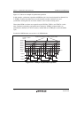
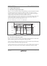
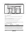
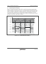
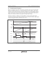
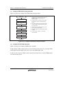
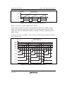
(2) Cascaded Operation Example (a)
Figure 11.21 illustrates the operation when TCNT_2 overflow/underflow counting has been set for
TCNT_1 and phase counting mode has been designated for channel 2.
TCNT_1 is incremented by TCNT_2 overflow and decremented by TCNT_2 underflow.