


Section 33 Power-Down Modes
R01UH0134EJ0400 Rev. 4.00 Page 1817 of 2108
Sep 24, 2014
SH7262 Group, SH7264 Group
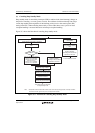
33.3.5 Module Standby Function
(1) Transition to Module Standby Function
Setting the standby control register MSTP bits to 1 halts the supply of clocks to the corresponding
on-chip peripheral modules. This function can be used to reduce the power consumption in the
program execution state and sleep mode. Disable a module before placing it in the module standby
mode. In addition, do not access the module's registers while it is in the module standby state.
For details on the states of registers, see section 36.3, Register States in Each Operating Mode.
(2) Canceling Module Standby Function
The module standby function can be canceled by clearing each MSTP bit to 0, or by a power-on
reset (only possible for the realtime clock, user debugging interface, and direct memory access
controller). When taking a module out of the module standby state by clearing the corresponding
MSTP bit to 0, read the MSTP bit to confirm that it has been cleared to 0.
33.3.6 Adjustment of XTAL Crystal Oscillator Gain
The gain of the crystal oscillator can be adjusted using the GAIN bit in XTALCTR. To modify the
gain, PLL settling time is needed. The settling time is counted using the on-chip watchdog timer.
1. The large gain is selected in the initial state.
2. Set the watchdog timer so that the specified settling time should be obtained and stop the
watchdog timer. Specifically, the following settings are necessary:
TME in WTCSR = 0: Stop the watchdog timer.
CKS[2:0] in WTCSR: Division ratio for watchdog timer count clock
WTCNT: Initial counter value
(The watchdog timer starts counting on the set clock.)
3. Set the GAIN bit to the desired value.
4. The LSI is internally stopped and the watchdog timer starts counting. The clock is supplied
only to the watchdog timer and other internal clocks are stopped. In this state, the CKIO pin
continues to output an unstable clock. To avoid malfunction due to the unstable clock, modify
the CKOEN2 bit in FRQCR appropriately. Since this state is equivalent to the software
standby mode state, some registers of on-chip peripheral modules are initialized. For details,
see section 36.3, Register States in Each Operating Mode.
5. When an overflow occurs on the watchdog timer, the specified clock supply is started and the
LSI starts operation. The watchdog timer stops after an overflow.