


Test points
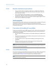
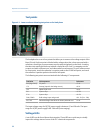
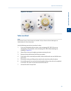
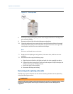
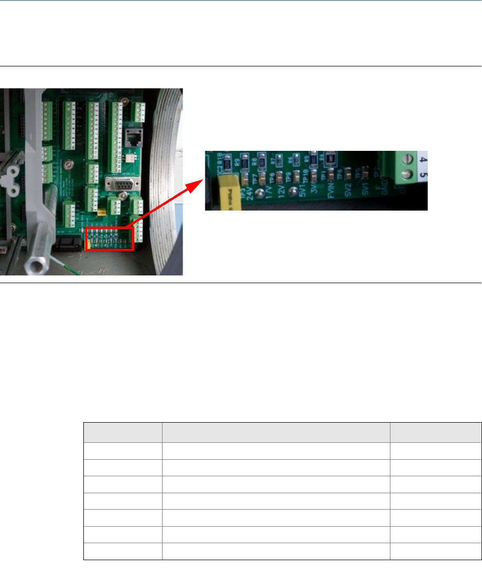
Lower enclosure showing test points on the back planeFigure 4-1:
The backplane has a set of test points that allow you to measure the voltage output of the
Base I/O card. Each test point is labeled with a voltage value that, when measured with a
voltmeter, should give a measurement equal to what is displayed on the label. A reading
that does not match this label may indicate a faulty Base I/O card. Try swapping out the
suspect card with a different one, and take another measurement. To get a measurement
for a test point, touch the voltmeter’s negative probe to the D GND test point, and touch
the voltmeter’s positive probe to the desired test point.
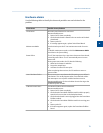
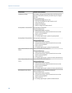
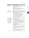
The following test points are associated with the following GC components:
Test Point GC Component Tolerances
24V (Regulated) GC power ±2.4V
17V Preamp (Input for the bridge circuit) ±0.5V
12V Optional I/O cards ±0.6V
5V1 System chips ±0.25V
3.3V System chips ±0.15V
FVIN, F GND Field voltage input and ground ±0V - 3V (21v - 30v)
SV1, SV2 Solenoid voltages that drive the heater/solenoid card ±2.4V
The input voltage range for DC/DC power supply is between 21 and 30 volts. The input
range for AC/DC power supply is 90 - 264 volts (auto-ranging).
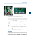
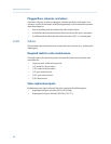
Voltage LEDs
A set of LEDs can be found above the test points. These LEDs are a quick way to visually
inspect the voltage status of some of the GC’s electrical components.
Operation and maintenance
86