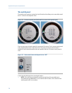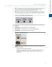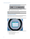
• 8 infrared-activated touch screen keys that eliminate the requirement for a
magnetic pen.
• Complete GC status, control and diagnostics, including full chromatogram display.
See Appendix A for more information about operating the LOI.
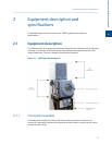
2.1.2 Upper compartment
The upper compartment contains the following components:
• Valves. There are two types of XA valves: 6-port and 10-port. A 700XA can have a
maximum of four XA valves consisting of any combination of the two types.
• Column module. Either capillary or micro-packed.
• Thermal conductivity detector (TCD). The 700XA has a minimum of one TCD and a
maximum of two TCDs.
• Two heating elements: a “top hat” heater and a column heater.
• One temperature switch for each heating element. The switch turns off its
heating element if the heating element reaches 257° F (160° C).
• Pressure switch. The pressure switch activates when the carrier pressure falls below
a predetermined set point. When activated, the switch triggers a general alarm that
displays on the front panel or LOI and in MON2020.
• Flame ionization detector (FID). The optional FID, which detects trace levels of
hydrocarbons, can be used in place of one TCD.
• Flame photometric detector (FPD). The optional FPD, which detects trace levels of
sulphur compounds, can be used in place of a TCD. Installed as a "side car"
component. For more information, refer to the FPD for Gas Chromatographs
Hardware Reference Manual.
• Methanator. The methanator, or catalytic converter, is an optional component that
converts otherwise undetectable carbon dioxide and/or carbon monoxide into
methane by adding hydrogen and heat to the sample.
• Liquid sample injection valve (LSIV). The optional LSIV is used to vaporize a liquid
sample, thereby expanding the GC’s capability to measure liquids.
2.1.3 Lower compartment
The lower compartment consists of the following components:
• Backplane. The backplane is the GC’s central printed circuit board (PCB). Its main
function is as a connection point for the GC’s specialized plug-in PCBs. The
backplane also hosts connections for analog outputs and analog inputs, serial ports
and an Ethernet port.
• Card cage. The card cage holds the specialized PCBs that plug into the backplane.
The following PCBs are housed in the card cage:
- Preamp board
- CPU board
- Base I/O board
Equipment description and specifications
2
Equipment description and specifications
19


