


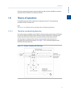
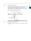

1.5.5 Data acquisition
Every second, exactly 50 equally spaced data samples are taken (i.e., one data sample
every 20 milliseconds) for analysis by the controller assembly.
As a part of the data acquisition process, groups of incoming data samples are averaged
together before the result is stored for processing. Non-overlapping groups of N samples
are averaged and stored, and thus reduce the effective incoming data rate to 40/N
samples per second. For example, if N = 5, then a total of 40/5 or 8 (averaged) data
samples are stored every second.
The value for the variable N is determined by the selection of a Peak Width parameter
(PW). The relationship is
N = PW
where PW is given in seconds. Allowable values of N are 1 to 63; this range corresponds to
PW values of 2 to 63 seconds.
The variable N is known as the integration factor. This term is used because N determines
how many points are averaged, or integrated, to form a single value. The integration of
data upon input, before storing, serves two purposes:
• The statistical noise on the input signal is reduced by the square root of N. In the
case of N = 4, a noise reduction of two would be realized.
• The integration factor controls the bandwidth of the chromatograph signal. It is
necessary to match the bandwidth of the input signal to that of the analysis
algorithms in the controller assembly. This prevents small, short-duration
perturbations from being recognized as true peaks by the program. It is therefore
important to choose a Peak Width that corresponds to the narrowest peak in the
group under consideration.
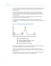
1.5.6 Peak detection
For normal area or peak height concentration evaluation, the determination of a peak's
start point and end point is automatic. The manual determination of start and end points is
used only for area calculations in the Forced Integration mode. Automatic determination
of peak onset or start is initiated whenever Integrate Inhibit is turned off. Analysis is started
in a region of signal quiescence and stability, such that the signal level and activity can be
considered as baseline values.
Note
The controller assembly software assumes that a region of signal quiescence and stability will exist.
Having initiated a peak search by turning Integrate Inhibit off, the controller assembly
performs a point by point examination of the signal slope. This is achieved by using a
digital slope detection filter, a combination low pass filter and differentiator. The output is
continually compared to a user-defined system constant called Slope Sensitivity. A default
value of 8 is assumed if no entry is made. Lower values make peak onset detection more
sensitive, and higher values make detection less sensitive. Higher values (20 to 100) would
be appropriate for noisy signals, e.g. high amplifier gain.
Introduction
1
Introduction
9