Dryers and Filters Use small sizes to minimize time lag and prevent back diffusion.
• Install a minimum of one filter to remove solid particles. Most applica-
tions require fine-element filters upstream of the GC. The GC includes a
2-micron filter.
• Do use ceramic or porous metallic type filters. Do not use cork or felt fil-
ters.
Note
Install the probe/regulator first, immediately followed by the coalescing fil-
ter and then the membrane filter. See Appendix B for a recommended natu-
ral gas installation.
Pressure Regula-
tors and Flow Con-
trollers
• Use stainless steel wetted materials.
• Should be rated for sample pressure and temperature.
Pipe Threads and
Dressings
Use Teflon tape. Do not use pipe thread compounds or pipe dope.
Valving • Install a block valve downstream of sample takeoff point for mainte-
nance and shutdown.
• The block valve should be a needle valve or cock valve type, of proper
material and packing, and rated for process line pressure.
3.4 Preparation
Your GC was started and inspected before it left the factory. Program parameters were
installed and documented in the GC Config Report furnished with your gas
chromatograph.
3.4.1 Site selection
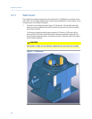
Install the GC as close as possible to the sample system but allow for adequate access
space for maintenance tasks and adjustments. Allow a minimum of 14 inches (36 cm) in
front for enclosure opening and access. Allow a minimum of 14 inches (36 cm) above the
top of the dome enclosure for dome removal and access.
Ensure that exposure to radio frequency (RF) interference is minimal.
3.4.2 Unpacking the unit
1. Unpack the equipment:
• 700XA
• CD-ROM containing software and manuals.
Installation and setup
3
Installation and setup
37


