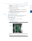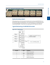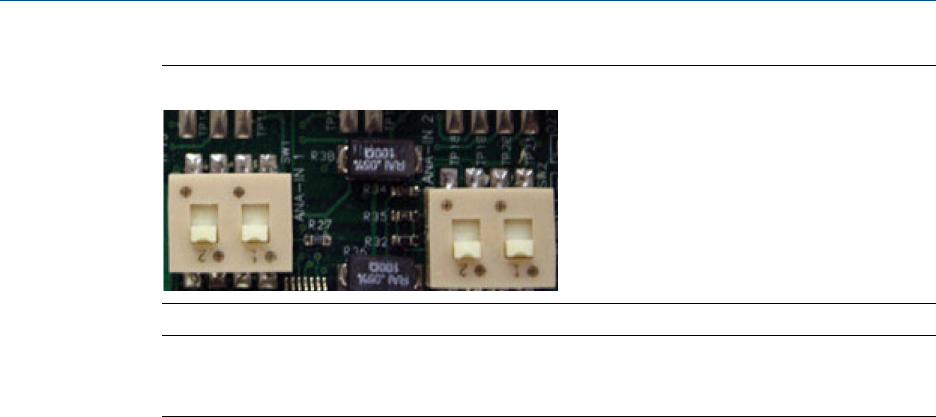
Factory settings for analog input switchesFigure 3-25:
Note
To set an analog input to accept a voltage (0-10 VDC) source, flip the appropriate switch in the
opposite direction from that shown in Figure 3-25.
Selecting the input type for an analog input
An analog input can be set to either voltage (0-10V) or current (4-20 mA) by flipping the
appropriate switches on the Base I/O board.
1. Turn off the GC.
2. Locate and remove the Base I/O board, which is in the card cage in the GC’s lower
enclosure.
3. To set analog input #1 to current, locate SW1 on the Base I/O board and push the
switches up, toward the card ejector; to set the analog input to voltage, push the
switches down, away from the card ejector.
4. To set analog input #2 to current, locate SW2 on the Base I/O board and push the
switches up, toward the card ejector; to set the analog input to voltage, push the
switches down, away from the card ejector.
5. Replace the Base I/O board in the card cage.
6. Start up the GC.
7. Start MON2020 and connect to the GC.
8. Select Analog Inputs from the Hardware menu. The Analog Inputs window displays.
9. To set the analog input to current, select mA from the mA/Volts drop-down list for
the appropriate analog input; to set the analog input to voltage, select Volts from
the mA/Volts drop-down list for the appropriate analog input.
10. Click Save to save the changes and keep the window open, or click OK to save the
changes and close the window.
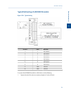
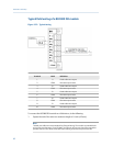
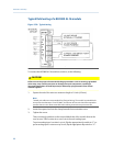
Typical wiring for line-powered transmitters
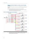
The following drawing shows the most common wiring plan for supplying power to two
4-20 mA transmitters, such as pressure sensor transmitters.
Installation and setup
64


