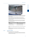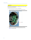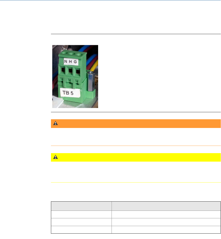
1. Locate the plug-together termination block inside the electronics enclosure, atop
the power supply and adjacent to the card cage.
AC/DC termination blockFigure 3-7:
WARNING!
Do not connect the AC power leads without first ensuring that AC power source is
switched OFF. Failure to follow this warning may result in injury or death to personnel or
cause damage to the equipment.
CAUTION!
Do not apply electrical power to the GC until all interconnections and external signal
connections have been verified, and proper grounds have been made. Failure to observe
this precaution may cause damage to equipment.
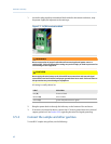
AC wiring is usually colored as:
Label Wire Color
Hot (H) brown or black
Neutral (N) blue or white
Ground (G) green with yellow tracer or green
2. Bring the power leads in through the left entry on the bottom of the enclosure.
3. If necessary at remote locations, connect the GC chassis ground wire to an external
copper ground rod. See Section 3.3.3 regarding electrical and signal grounding.
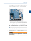
3.5.3 Connect the sample and other gas lines
To install GC sample and gas lines, do the following:
Installation and setup
42


