


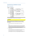
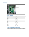

Terminal Label Definition
6 COM Analog output return
7 4+ Positive analog output
8 COM Analog output return
9 N/A Not used
10 N/a Not used
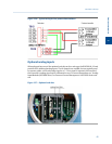
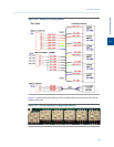
To connect the ROC800 AO module to a field device, do the following:
1. Expose the end of the wire to a maximum length of ¼ inch (6.3mm).
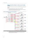
Note
Twisted-pair cables are recommended for I/O signal wiring. The module’s terminal blocks
accept wire sizes between 12 and 22 AWG. A minimum of bare wire should be exposed to
prevent short circuits. Allow some slack when making connections to prevent strain.
2. Insert the exposed end into the clamp beneath the termination screw.
3. Tighten the screw.
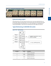
3.6 Leak checking and purging for first calibration
Verify that all electrical connections are correct and safe, and then turn the unit on.
3.6.1 Checking the GC for leaks
To perform a leak check, do the following:
1. Plug all vents.
2. Make sure the setting of the carrier gas cylinder gauge is 115 psig and/or the valve
actuation pressure is between 110 and 120 psig.
3. Check all fittings at the pressure gauge flow panel and at the carrier gas cylinder
gauge with a leak detector. Correct any leaks detected.
4. Turn the carrier gas cylinder shut-off valve clockwise to close. Observe the carrier
gas pressure for ten minutes to check for a drop in carrier pressure. The drop should
be less than 200 psig on the high side of the gauge. If the carrier gas is lost at a faster
rate, check for leaks between the carrier gas bottle and the analyzer.
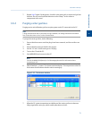
5. Use the LOI or MON2020 to actuate the valves on and off and observe the pressure
with the valves in different positions than in Step 4. When the valves are switched,
some pressure change is normal because of carrier loss. Momentarily open cylinder
valve to restore pressure if necessary.
6. If the pressure does not hold relatively constant, check all valve fittings for tightness.
Installation and setup
72