


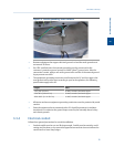
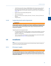
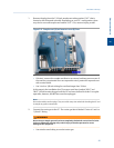
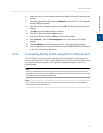
1. Remove the plug from the 1/16-inch sample vent tubing marked “SV1” that is
located on the flow panel assembly. Depending on your GC’s configuration, there
may also be a second sample vent marked “SV2”. If so, remove its plug as well.
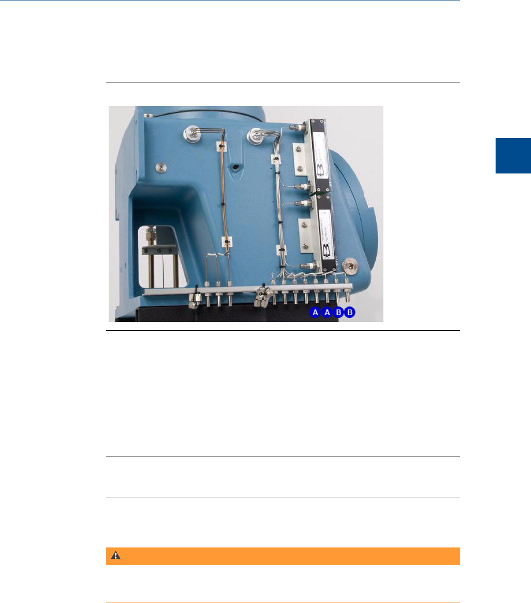
Sample vent (A) and measure vent (B) linesFigure 3-8:
• If desired, connect the sample vent lines to an external, ambient pressure vent. If
the vent line is terminated in an area exposed to wind, protect the exposed vent
with a metal shield.
• Use ¼-inch or 3/8-inch tubing for vent lines longer than 10 feet.
At this stage in the installation the GC measure vent lines (marked “MV1” and
“MV2”) should remain plugged until the GC has been checked for leaks. For regular
operation, however, the MV lines must be unplugged.
Note
Do not discard the vent line plugs. They are useful at any time when leak-checking the GC and
its sample or gas line connections.
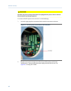
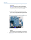
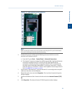
2. Connect the carrier gas to the GC. The carrier gas inlet is labeled “Carrier In” and is a
1/8-inch T-fitting.
WARNING!
Do not turn on sample gas until you have completely checked the carrier lines for leaks.
Failure to follow this warning may result in injury or death to personnel or cause
damage to the equipment.
• Use stainless steel tubing to conduct carrier gas.
Installation and setup
3
Installation and setup
43