


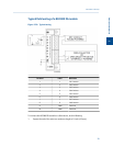
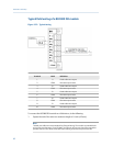
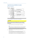
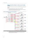
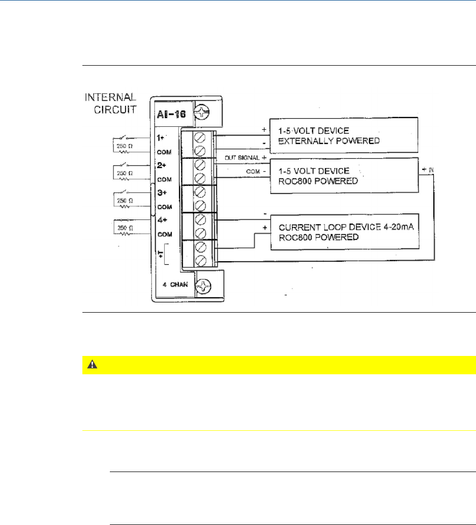
Typical field wiring of a ROC800 AI-16 module
Typical wiringFigure 3-28:
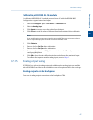
To connect the ROC800 AI-16 module to a device, do the following:
CAUTION!
Failure to exercise proper electrostatic discharge precautions—such as wearing a grounded
wrist strap—may reset the processor or damage electronic components, resulting in
interrupted operations. Ground loops may be induced by tying commons from various
modules together.
1. Expose the end of the wire to a maximum length of ¼ inch (6.3mm).
Note
Twisted-pair cables are recommended for I/O signal wiring. The module’s terminal blocks
accept wire sizes between 12 and 22 AWG. A minimum of bare wire should be exposed to
prevent short circuits. Allow some slack when making connections to prevent strain.
2. Insert the exposed end into the clamp beneath the termination screw.
3. Tighten the screw.
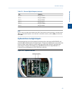
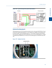
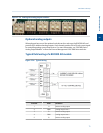
There are two dip switches on the terminal block side of the module that can be
used to set a 250 Ω resistor in or out of circuit for each analog input.
To put an analog input’s resistor in circuit, flip the appropriate dip switch to “I”; to
put an analog input’s resistor out of circuit, flip the appropriate dip switch to “V”.
Installation and setup
66