Note
Twisted-pair cables are recommended for I/O signal wiring. The module’s terminal blocks
accept wire sizes between 12 and 22 AWG. A minimum of bare wire should be exposed to
prevent short circuits. Allow some slack when making connections to prevent strain.
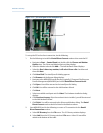
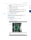
2. Insert the exposed end into the clamp beneath the termination screw.
3. Tighten the screw.
Discrete digital outputs
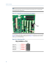
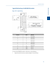
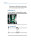
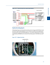
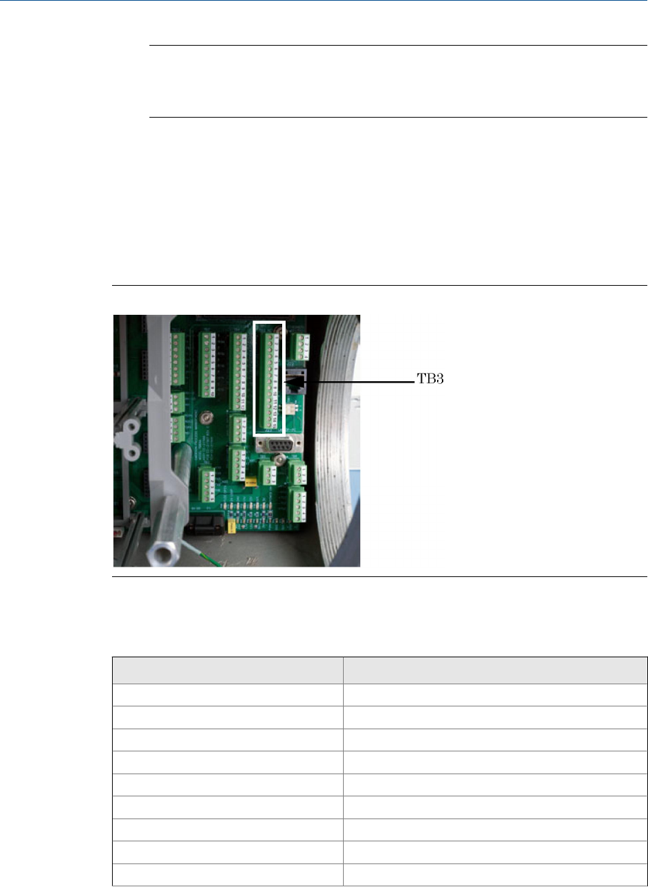
The discrete outputs are located on TB3, which is a 15-pin Phoenix connector, and have
five Form-C relays on the back plane. All contact outputs have a rating of 1A @30 VDC.
TB3 on the backplaneFigure 3-21:
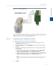
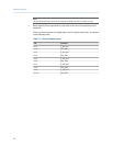
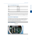
Table 3-2 lists the discrete digital output function for each pin on the TB3 connector.
Discrete Digital OutputsTable 3-2:
TB3 Function
Pin 1 DIG_OUT NC1
Pin 2 DIG_OUT ARM1
Pin 3 DIG_OUT NO1
Pin 4 DIG_OUT NC2
Pin 5 DIG_OUT ARM2
Pin 6 DIG_OUT NO2
Pin 7 DIG_OUT NC3
Pin 8 DIG_OUT ARM3
Pin 9 DIG_OUT NO3
Installation and setup
60


