and can be configured to auto zero anytime during the analysis if the
component is not eluting or the baseline is steady. The TCD is only
auto zeroed at the start of a new analysis.
Baseline Signal output when there is only carrier gas going across the
detectors. In a chromatogram you should only see Baseline when
running an analysis without injecting a sample.
Carrier gas The gas used to push the sample through the system during an
analysis. In C6+ analysis we use Ultra Pure (zero grade) Carrier Gas for
the carrier. This gas is 99.995 percent pure.
Chromatogram A permanent record of the detector output. A chromatogram is
obtained from a PC interfaced with the detector output through the
controller assembly. A typical chromatogram displays all component
peaks, and gain changes. It may be viewed in color as it is processed
on a PC VGA display. Tick marks recorded on the chromatogram by
the controller assembly indicate where timed events take place.
Component Any one of several different gases that may appear in a sample
mixture. For example, natural gas usually contains the following
components: nitrogen, carbon dioxide, methane, ethane, propane,
isobutane, normal butane, isopentane, normal pentane, and hexanes
plus.
CTS Clear to send.
DCD Data carrier detect.
DSR Data set ready.
DTR Data terminal ready.
FID Flame ionization detector. The optional FID may be used in place of a
TCD for the detection of trace compounds. The FID requires a
polarization voltage and its output is connected to the input to a high
impedance amplifier, an electrometer. The sample of gas to be
measured is injected into the burner with a mixture of hydrogen and
air to maintain the flame.
LSIV Liquid sample injection valve. The optional LSIV is used to convert a
liquid sample to a gas sample by vaporizing the liquid in a heated
chamber, then analyzing the flashed sample.
Methanator The optional methanator, also known as a catalytic converter,
transforms otherwise undetectable carbon dioxide and/or carbon
monoxide into methane by adding hydrogen and heat to the sample.
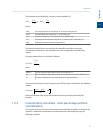
Response factor Correction factor for each component as determined by the following
calibration:
RF =
RawArea
Calibration Concentration
Retention time Time, in seconds, that elapses between the start of analysis and the
sensing of the maximum concentration of each component by the
detector.
RI Ring indicator.
RLSD Received line signal detect. A digital simulation of a carrier detect.
RTS Request to send.
Introduction
1
Introduction
13


