


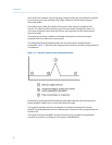


Onset is defined where the detector output exceeds the baseline constant, but peak
termination is defined where the detector output is less than the same constant.
Sequences of fused peaks are also automatically handled. This is done by testing each
termination point to see if the region immediately following it satisfies the criteria of a
baseline. A baseline region must have a slope detector value less than the magnitude of
the baseline constant for a number of sequential points. When a baseline region is found,
this terminates a sequence of peaks.
A zero reference line for peak height and area determination is established by extending a
line from the point of the onset of the peak sequence to the point of the termination. The
values of these two points are found by averaging the four integrated points just prior to
the onset point and just after the termination points, respectively.
The zero reference line will, in general, be non-horizontal, and thus compensates for any
linear drift in the system from the time the peak sequence starts until it ends.
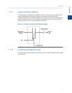
In a single peak situation, peak area is the area of the component peak between the curve
and the zero reference line. The peak height is the distance from the zero reference line to
the maximum point on the component curve. The value and location of the maximum
point is determined from quadratic interpolation through the three highest points at the
peak of the discrete valued curve stored in the controller assembly.
For fused peak sequences, this interpolation technique is used both for peaks, as well as,
valleys (minimum points). In the latter case, lines are dropped from the interpolated valley
points to the zero reference line to partition the fused peak areas into individual peaks.
The use of quadratic interpolation improves both area and height calculation accuracy and
eliminates the effects of variations in the integration factor on these calculations.
For calibration, the controller assembly may average several analyses of the calibration
stream.
1.6 Basic analysis computations
Two basic analysis algorithms are included in the controller assembly:
• Area Analysis – calculates area under component peak
• Peak Height Analysis – measures height of component peak
Note
For additional information about other calculations performed, see the MON2020 user manual.
1.6.1 Concentration analysis - response factor
Concentration calculations require a unique response factor for each component in an
analysis. These response factors may be manually entered by an operator or determined
automatically by the system through calibration procedures (with a calibration gas mixture
that has known concentrations).
Introduction
10