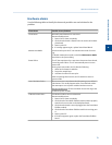
Hardware alarms
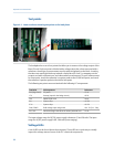
Use the following table to identify the alarm and possible cause and solution for the
problem.
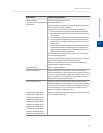
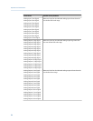
Alarm Name Possible Causes/Solution
LTLOI Failure No switch panel detected or connected.
Recommended actions:
1. Power the GC down completely.
2. Check that the board is seated in the correct slot of the back-
plane board.
3. Power up the GC.
4. If message appears again, replace Switch Panel Board.
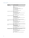
Maintenance Mode A technician has put the GC into maintenance mode for servic-
ing.
To disable maintenance mode, unclick the Maintenance Mode
check box in the System dialog.
Power Failure The GC has experienced a re-start since alarms were last cleared,
caused by power failure. The GC automatically starts in warm
start mode.
During warm start mode, the GC does the following:
1. Waits for the heaters to stabilize.
2. Purges the sample loop.
3. Actuates the valves for two cycles.
After completing these actions, the GC switches to auto-se-
quence mode.
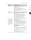
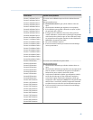
User Calculation Failure One or more errors were detected while parsing a user-defined
calculations. This usually happens when a user-defined calcula-
tion attempts to use a system variable that does not exist.
Recommended action: Fix the calculation that is referring to the
undefined system variable.
FF Board Comm Failure Foundation Fieldbus board not detected.
Recommended actions:
1. Power the GC down completely.
2. Check that the Foundation Fieldbus module cable is properly
seated in the correct slot on the backplane board.
3. Check that the board is securely plugged into the Foundation
Fieldbus module.
4. Check that the Foundation Fieldbus module is receiving pow-
er.
5. Power up the GC.
6. If the alarm appears again, replace the Foundation Fieldbus
board.
Operation and maintenance
4
Operation and maintenance
79


