


37-22
Catalyst 2960 and 2960-S Switch Software Configuration Guide
OL-8603-09
Chapter 37 Configuring EtherChannels and Link-State Tracking
Understanding Link-State Tracking
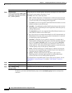
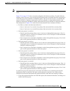
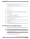
• If all of the upstream interfaces become unavailable, link-state tracking automatically puts the
downstream interfaces in the error-disabled state. Connectivity to and from the servers is
automatically changed from the primary server interface to the secondary server interface.
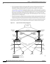
As an example of a connectivity change from link-state group 1 to link-state group 2 on switch A,
see Figure 37-6 on page 37-22. If the upstream link for port 6 is lost, the link states of downstream
ports 1 and 2 do not change. However, if the link for upstream port 5 is also lost, the link state of the
downstream ports changes to the link-down state. Connectivity to server 1 and server 2 is then
changed from link-state group1 to link-state group 2. The downstream ports 3 and 4 do not change
state because they are in link-group 2.
• If the link-state group is configured, link-state tracking is disabled, and the upstream interfaces lose
connectivity, the link states of the downstream interfaces remain unchanged. The server does not
recognize that upstream connectivity has been lost and does not failover to the secondary interface.
You can recover a downstream interface link-down condition by removing the failed downstream port
from the link-state group. To recover multiple downstream interfaces, disable the link-state group.
Figure 37-6 Typical Link-State Tracking Configuration
141680
Network
Layer 3 link
Server 1 Server 2 Server 3 Server 4
Distribution
switch 1
Distribution
switch 2
Switch A Switch B
Port
1
Port
5
Port
4
Port
3
Port
2
Port
2
Port
3
Port
4
Port
8
Port
7
Port
6
Port
5
Port
1
Port
6
Port
7
Port
8
Link-
state
group 2
Link-state
group 1
Link-state
group 1
Link-state
group 2
Link-state
group 2
Link-
state
group 1
Link-
state
group 1
Primary link
Secondary link
Link-
state
group 2