


CHAPTER
16-1
Catalyst 2960 and 2960-S Switch Software Configuration Guide
OL-8603-09
16
Configuring STP
This chapter describes how to configure the Spanning Tree Protocol (STP) on port-based VLANs on the
Catalyst 2960 and 2960-S switches. The switch can use either the per-VLAN spanning-tree plus
(PVST+) protocol based on the IEEE 802.1D standard and Cisco proprietary extensions, or the rapid
per-VLAN spanning-tree plus (rapid-PVST+) protocol based on the IEEE 802.1w standard. A switch
stack appears as a single spanning-tree node to the rest of the network, and all stack members use the
same bridge ID. Unless otherwise noted, the term switch refers to a standalone switch and to a switch
stack.
Note Stacking is supported only on Catalyst 2960-S switches running the LAN base image.
For information about the Multiple Spanning Tree Protocol (MSTP) and how to map multiple VLANs
to the same spanning-tree instance, see Chapter 17, “Configuring MSTP.” For information about other
spanning-tree features such as Port Fast, UplinkFast, root guard, and so forth, see Chapter 18,
“Configuring Optional Spanning-Tree Features.”
Note For complete syntax and usage information for the commands used in this chapter, see the command
reference for this release.
This chapter consists of these sections:
• Understanding Spanning-Tree Features, page 16-1
• Configuring Spanning-Tree Features, page 16-12
• Displaying the Spanning-Tree Status, page 16-24
Understanding Spanning-Tree Features
These sections contain this conceptual information:
• STP Overview, page 16-2
• Spanning-Tree Topology and BPDUs, page 16-3
• Bridge ID, Switch Priority, and Extended System ID, page 16-4
• Spanning-Tree Interface States, page 16-5
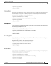
• How a Switch or Port Becomes the Root Switch or Root Port, page 16-8
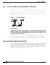
• Spanning Tree and Redundant Connectivity, page 16-8