


13-10
Catalyst 2960 and 2960-S Switch Software Configuration Guide
OL-8603-09
Chapter 13 Configuring VLANs
Configuring Extended-Range VLANs
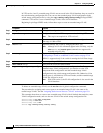
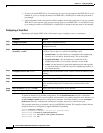
Beginning in privileged EXEC mode, follow these steps to assign a port to a VLAN in the VLAN
database:
To return an interface to its default configuration, use the default interface interface-id interface
configuration command.
This example shows how to configure a port as an access port in VLAN 2:
Switch# configure terminal
Enter configuration commands, one per line. End with CNTL/Z.
Switch(config)# interface gigabitethernet0/1
Switch(config-if)# switchport mode access
Switch(config-if)# switchport access vlan 2
Switch(config-if)# end
Configuring Extended-Range VLANs
With VTP version 1 and version 2, when the switch is in VTP transparent mode (VTP disabled), you can
create extended-range VLANs (in the range 1006 to 4094). VTP version supports extended-range
VLANs in server or transparent move. Extended-range VLANs enable service providers to extend their
infrastructure to a greater number of customers. The extended-range VLAN IDs are allowed for any
switchport commands that allow VLAN IDs.
With VTP version 1 or 2, extended-range VLAN configurations are not stored in the VLAN database,
but because VTP mode is transparent, they are stored in the switch running configuration file, and you
can save the configuration in the startup configuration file by using the copy running-config
startup-config privileged EXEC command. Extended-range VLANs created in VTP version 3 are stored
in the VLAN database.
Note Although the switch supports 4094 VLAN IDs, see the “Supported VLANs” section on page 13-2 for
the actual number of VLANs supported.
These sections contain extended-range VLAN configuration information:
• Default VLAN Configuration, page 13-11
• Extended-Range VLAN Configuration Guidelines, page 13-11
• Creating an Extended-Range VLAN, page 13-11
Command Purpose
Step 1
configure terminal Enter global configuration mode
Step 2
interface interface-id Enter the interface to be added to the VLAN.
Step 3
switchport mode access Define the VLAN membership mode for the port (Layer 2 access
port).
Step 4
switchport access vlan vlan-id Assign the port to a VLAN. Valid VLAN IDs are 1 to 4094.
Step 5
end Return to privileged EXEC mode.
Step 6
show running-config interface interface-id Verify the VLAN membership mode of the interface.
Step 7
show interfaces interface-id switchport Verify your entries in the Administrative Mode and the Access Mode
VLAN fields of the display.
Step 8
copy running-config startup-config (Optional) Save your entries in the configuration file.