


34-2
Catalyst 2960 and 2960-S Switch Software Configuration Guide
OL-8603-09
Chapter 34 Configuring Static IP Unicast Routing
Understanding IP Routing
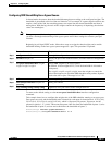
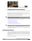
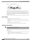
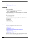
Figure 34-1 Routing Topology Example
When Host A in VLAN 10 needs to communicate with Host B in VLAN 10, it sends a packet addressed
to that host. Switch A forwards the packet directly to Host B, without sending it to the router.
When Host A sends a packet to Host C in VLAN 20, Switch A forwards the packet to the router, which
receives the traffic on the VLAN 10 interface. The router uses the routing table to finds the correct
outgoing interface, and forwards the packet on the VLAN 20 interface to Switch B. Switch B receives
the packet and forwards it to Host C.
When static routing is enabled on Switch A and B, the router device is no longer needed to route packets.
Types of Routing
Routers and Layer 3 switches can route packets in these ways:
• Using default routing to send traffic with a destination unknown to the router to a default outlet
or destination
• Using static routes to forward packets from predetermined ports through a single path into and out
of a network
• Dynamically calculating routes by using a routing protocol
The switch supports static routes and default routes, It does not support routing protocols.
IP Routing and Switch Stacks
Note Stacking is supported only on Catalyst 2960-S switches.
A switch stack appears to the network as a single switch, regardless of which switch in the stack is
connected to a peer. For additional information about switch stack operation, see Chapter 7, “Managing
Switch Stacks.”
Stack master functions:
• The MAC address of the stack master is used as the router MAC address for the whole stack, and all
outside devices use this address to send IP packets to the stack.
• All IP packets that require software forwarding or processing go through the CPU of the stack
master.
18071
A
B
C
Host
Host
Host
Switch A Switch B
VLAN 10 VLAN 20
ISL Trunks