


CHAPTER
13-1
Catalyst 2960 and 2960-S Switch Software Configuration Guide
OL-8603-09
13
Configuring VLANs
This chapter describes how to configure normal-range VLANs (VLAN IDs 1 to 1005) and
extended-range VLANs (VLAN IDs 1006 to 4094) on the Catalyst 2960 and 2960-S switches. It includes
information about VLAN membership modes, VLAN configuration modes, VLAN trunks, and dynamic
VLAN assignment from a VLAN Membership Policy Server (VMPS). Unless otherwise noted, the term
switch refers to a standalone switch and a switch stack.
Note Stacking is supported only on Catalyst 2960-S switches running the LAN base image.
Note For complete syntax and usage information for the commands used in this chapter, see the command
reference for this release.
The chapter consists of these sections:
• Understanding VLANs, page 13-1
• Configuring Normal-Range VLANs, page 13-4
• Configuring Extended-Range VLANs, page 13-10
• Displaying VLANs, page 13-13
• Configuring VLAN Trunks, page 13-13
• Configuring VMPS, page 13-22
Understanding VLANs
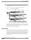
A VLAN is a switched network that is logically segmented by function, project team, or application,
without regard to the physical locations of the users. VLANs have the same attributes as physical LANs,
but you can group end stations even if they are not physically located on the same LAN segment. Any
switch port can belong to a VLAN, and unicast, broadcast, and multicast packets are forwarded and
flooded only to end stations in the VLAN. Each VLAN is considered a logical network, and packets
destined for stations that do not belong to the VLAN must be forwarded through a router or a switch
supporting fallback bridging, as shown in Figure 13-1. VLANs can be formed with ports across the
stack. Because a VLAN is considered a separate logical network, it contains its own bridge Management
Information Base (MIB) information and can support its own implementation of spanning tree. See
Chapter 16, “Configuring STP.”