


33-16
Catalyst 2960 and 2960-S Switch Software Configuration Guide
OL-8603-09
Chapter 33 Configuring QoS
Understanding QoS
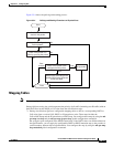
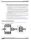
The switch supports two configurable ingress queues, which are serviced by SRR in shared mode only.
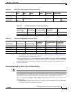
Table 33-1 describes the queues.
Note Catalyst 2960-S switches do not support ingress queueing.
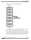
You assign each packet that flows through the switch to a queue and to a threshold. Specifically, you map
DSCP or CoS values to an ingress queue and map DSCP or CoS values to a threshold ID. You use the
mls qos srr-queue input dscp-map queue queue-id {dscp1...dscp8 | threshold threshold-id
dscp1...dscp8} or the mls qos srr-queue input cos-map queue queue-id {cos1...cos8 | threshold
threshold-id cos1...cos8} global configuration command. You can display the DSCP input queue
threshold map and the CoS input queue threshold map by using the show mls qos maps privileged EXEC
command.
WTD Thresholds
Note Catalyst 2960-S switches do not support ingress queueing.
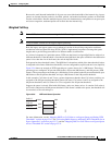
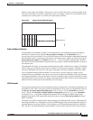
The queues use WTD to support distinct drop percentages for different traffic classes. Each queue has
three drop thresholds: two configurable (explicit) WTD thresholds and one nonconfigurable (implicit)
threshold preset to the queue-full state. You assign the two explicit WTD threshold percentages for
threshold ID 1 and ID 2 to the ingress queues by using the mls qos srr-queue input threshold queue-id
threshold-percentage1 threshold-percentage2 global configuration command. Each threshold value is a
percentage of the total number of allocated buffers for the queue. The drop threshold for threshold ID 3
is preset to the queue-full state, and you cannot modify it. For more information about how WTD works,
see the “Weighted Tail Drop” section on page 33-13.
Buffer and Bandwidth Allocation
Note Catalyst 2960-S switches do not support ingress queueing.
You define the ratio (allocate the amount of space) with which to divide the ingress buffers between the
two queues by using the mls qos srr-queue input buffers percentage1 percentage2 global configuration
command. The buffer allocation together with the bandwidth allocation control how much data can be
buffered and sent before packets are dropped. You allocate bandwidth as a percentage by using the mls
qos srr-queue input bandwidth weight1 weight2 global configuration command. The ratio of the
weights is the ratio of the frequency in which the SRR scheduler sends packets from each queue.
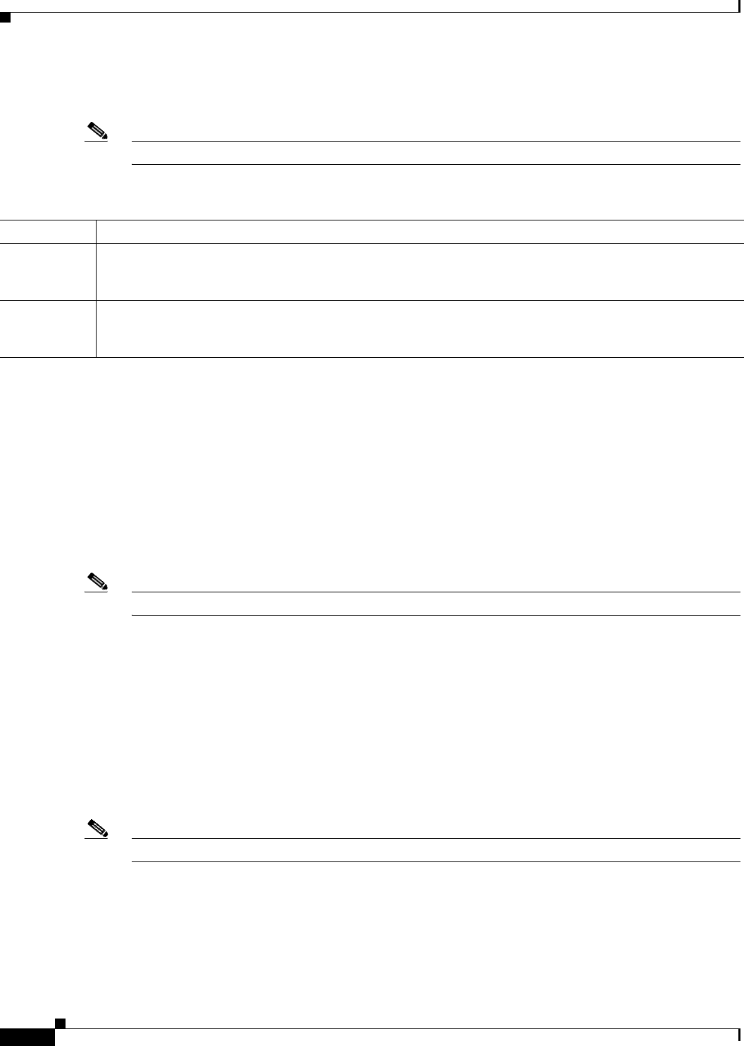
Table 33-1 Ingress Queue Types
Queue Type
1
1. The switch uses two nonconfigurable queues for traffic that is essential for proper network and stack operation.
Function
Normal User traffic that is considered to be normal priority. You can configure three different thresholds to
differentiate among the flows. You can use the mls qos srr-queue input threshold, the mls qos srr-queue
input dscp-map, and the mls qos srr-queue input cos-map global configuration commands.
Expedite High-priority user traffic such as differentiated services (DF) expedited forwarding or voice traffic. You can
configure the bandwidth required for this traffic as a percentage of the total stack traffic by using the mls qos
srr-queue input priority-queue global configuration command. The expedite queue has guaranteed bandwidth.