


12-10
Catalyst 2960 and 2960-S Switch Software Configuration Guide
OL-8603-09
Chapter 12 Configuring Interface Characteristics
Understanding Interface Types
Because the switch supports internal power supplies and the Cisco Redundant Power System 2300 (also
referred to as the RPS 2300), the total amount of power available for the powered devices varies
depending on the power supply configuration.
• If a power supply is removed and replaced by a new power supply with less power and the switch
does not have enough power for the powered devices, the switch denies power to the PoE ports that
are in auto mode in descending order of the port numbers. If the switch still does not have enough
power, it denies power to the PoE ports in static mode in descending order of the port numbers.
• If the new power supply supports more power than the previous one and the switch now has more
power available, the switch grants power to the PoE ports in static mode in ascending order of the
port numbers. If it still has power available, the switch then grants power to the PoE ports in auto
mode in ascending order of the port numbers.
For configuration information, see the “Configuring Power Policing” section on page 12-33.
Connecting Interfaces
Devices within a single VLAN can communicate directly through any switch. Ports in different VLANs
cannot exchange data without going through a routing device.
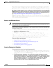
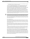
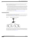
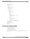
In the configuration shown in Figure 12-1, when Host A in VLAN 20 sends data to Host B in VLAN 30,
the data must go from Host A to the switch, to the router, back to the switch, and then to Host B.
Figure 12-1 Connecting VLANs with Layer 2 Switches
With a standard Layer 2 switch, ports in different VLANs have to exchange information through a router.
By using the switch with routing enabled, when you configure both VLAN 20 and VLAN 30 with an
SVI to which an IP address is assigned, packets can be sent from Host A to Host B directly through the
switch with no need for an external router (Figure 12-2).
Host A
Switch
Cisco router
VLAN 20
Host B
VLAN 30
46647