


CHAPTER
34-1
Catalyst 2960 and 2960-S Switch Software Configuration Guide
OL-8603-09
34
Configuring Static IP Unicast Routing
This chapter describes how to configure IP Version 4 (IPv4) static IP unicast routing on the Catalyst
2960-S and 2960 switch. Static routing is supported only on switched virtual interfaces (SVIs) and not
on physical interfaces. The switch does not support routing protocols.
Unless otherwise noted, the term switch refers to a standalone switch and a switch stack. A switch stack
operates and appears as a single switch to the routers in the network.
Note Stacking is supported only on Catalyst 2960-S switches.
For complete syntax and usage information for the commands used in this chapter, see the Cisco IOS IP
Command Reference, Volume 1 of 3: Addressing and Services, Release 12.2
• Understanding IP Routing, page 34-1
• Steps for Configuring Routing, page 34-3
• Enabling IP Unicast Routing, page 34-4
• Configuring Static Unicast Routes, page 34-5
• Monitoring and Maintaining the IP Network, page 34-5
Note When configuring routing parameters on the switch and to allocate system resources to maximize the
number of unicast routes allowed, use the sdm prefer lanbase-routing global configuration command
to set the Switch Database Management (SDM) feature to the routing template. For more information on
the SDM templates, see Chapter 8, “Configuring SDM Templates” or see the sdm prefer command in
the command reference for this release.
Understanding IP Routing
In some network environments, VLANs are associated with individual networks or subnetworks. In an
IP network, each subnetwork is mapped to an individual VLAN. Configuring VLANs helps control the
size of the broadcast domain and keeps local traffic local. However, network devices in different VLANs
cannot communicate with one another without a Layer 3 device to route traffic between the VLANs,
referred to as inter-VLAN routing. You configure one or more routers to route traffic to the appropriate
destination VLAN.
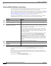
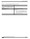
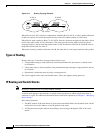
Figure 34-1 shows a basic routing topology. Switch A is in VLAN 10, and Switch B is in VLAN 20. The
router has an interface in each VLAN.