


19-2
Catalyst 2960 and 2960-S Switch Software Configuration Guide
OL-8603-09
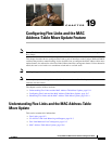
Chapter 19 Configuring Flex Links and the MAC Address-Table Move Update Feature
Understanding Flex Links and the MAC Address-Table Move Update
Flex Links
Flex Links are a pair of a Layer 2 interfaces (switch ports or port channels) where one interface is
configured to act as a backup to the other. The feature provides an alternative solution to the Spanning
Tree Protocol (STP). Users can disable STP and still retain basic link redundancy. Flex Links are
typically configured in service provider or enterprise networks where customers do not want to run STP
on the switch. If the switch is running STP, Flex Links is not necessary because STP already provides
link-level redundancy or backup.
You configure Flex Links on one Layer 2 interface (the active link) by assigning another Layer 2
interface as the Flex Link or backup link. The Flex Link can be on the same switch or on another switch
in the stack. When one of the links is up and forwarding traffic, the other link is in standby mode, ready
to begin forwarding traffic if the other link shuts down. At any given time, only one of the interfaces is
in the linkup state and forwarding traffic. If the primary link shuts down, the standby link starts
forwarding traffic. When the active link comes back up, it goes into standby mode and does not forward
traffic. STP is disabled on Flex Link interfaces.
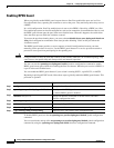
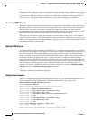
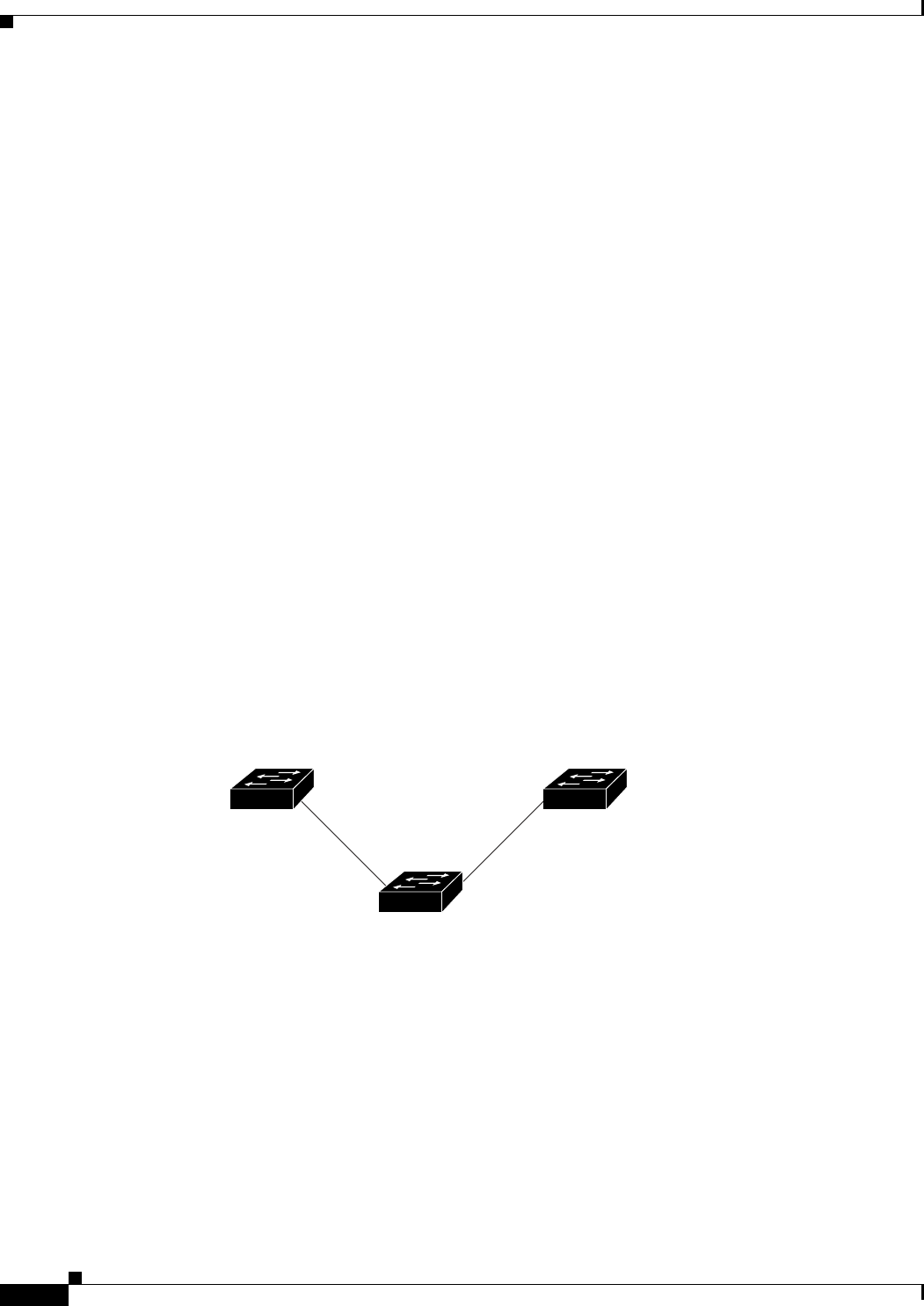
In Figure 19-1, ports 1 and 2 on switch A are connected to uplink switches B and C. Because they are
configured as Flex Links, only one of the interfaces is forwarding traffic; the other is in standby mode.
If port 1 is the active link, it begins forwarding traffic between port 1 and switch B; the link between
port 2 (the backup link) and switch C is not forwarding traffic. If port 1 goes down, port 2 comes up and
starts forwarding traffic to switch C. When port 1 comes back up, it goes into standby mode and does
not forward traffic; port 2 continues forwarding traffic.
You can also choose to configure a preemption mechanism, specifying the preferred port for forwarding
traffic. For example, in the example in Figure 19-1, you can configure the Flex Links pair with
preemption mode. In the scenario shown, when port 1 comes back up and has more bandwidth than port
2, port 1 begins forwarding traffic after 60 seconds. Port 2 becomes the standby port. You do this by
entering the interface configuration switchport backup interface preemption mode bandwidth and
switchport backup interface preemption delay commands.
Figure 19-1 Flex Links Configuration Example
If a primary (forwarding) link goes down, a trap notifies the network management stations. If the standby
link goes down, a trap notifies the users.
Flex Links are supported only on Layer 2 ports and port channels, not on VLANs.
Switch A
Uplink
switch B
Port 1 Port 2
Uplink
switch C
116082