


12-11
Catalyst 2960 and 2960-S Switch Software Configuration Guide
OL-8603-09
Chapter 12 Configuring Interface Characteristics
Using the Switch USB Ports (Catalyst 2960-S Switches Only)
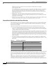
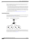
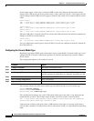
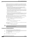
Figure 12-2 Connecting VLANs with a Layer 3 Switch
Using the Switch USB Ports (Catalyst 2960-S Switches Only)
The Catalyst 2960-S switch has two USB ports on the front panel:
• USB Mini-Type B Console Port, page 12-11
• USB Type A Port, page 12-14
USB Mini-Type B Console Port
The switch has two console ports available—a USB mini-Type B console connection and an RJ-45
console port. Console output appears on devices connected to both ports, but console input is active on
only one port at a time. The USB connector takes precedence over the RJ-45 connector.
Note Windows PCs require a driver for the USB port. See the hardware installation guide for driver
installation instructions.
Use the supplied USB Type A-to-USB mini-Type B cable to connect a PC or other device to the switch.
The connected device must include a terminal emulation application. When the switch detects a valid
USB connection to a powered-on device that supports host functionality (such as a PC), input from the
RJ-45 console is immediately disabled, and input from the USB console is enabled. Removing the USB
connection immediately reenables input from the RJ-45 console connection. An LED on the switch
shows which console connection is in use.
Console Port Change Logs
At software startup, a log shows whether the USB or the RJ-45 console is active. Each switch in a stack
issues this log. Every switch always first displays the RJ-45 media type.
Host A
SVI 1172.20.128.1 172.20.129.1SVI 2
Layer 3 switch
with routing enabled
VLAN 20
Host B
VLAN 30
101350