


13-15
Catalyst 2960 and 2960-S Switch Software Configuration Guide
OL-8603-09
Chapter 13 Configuring VLANs
Configuring VLAN Trunks
Default Layer 2 Ethernet Interface VLAN Configuration
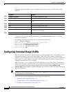
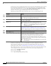
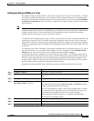
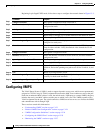
Table 13-5 shows the default Layer 2 Ethernet interface VLAN configuration.
Configuring an Ethernet Interface as a Trunk Port
Because trunk ports send and receive VTP advertisements, to use VTP you must ensure that at least one
trunk port is configured on the switch and that this trunk port is connected to the trunk port of a second
switch. Otherwise, the switch cannot receive any VTP advertisements.
These sections contain this configuration information:
• Interaction with Other Features, page 13-15
• Defining the Allowed VLANs on a Trunk, page 13-17
• Changing the Pruning-Eligible List, page 13-18
• Configuring the Native VLAN for Untagged Traffic, page 13-18
Interaction with Other Features
Trunking interacts with other features in these ways:
• A trunk port cannot be a secure port.
• Trunk ports can be grouped into EtherChannel port groups, but all trunks in the group must have the
same configuration. When a group is first created, all ports follow the parameters set for the first
port to be added to the group. If you change the configuration of one of these parameters, the switch
propagates the setting you entered to all ports in the group:
–
allowed-VLAN list.
–
STP port priority for each VLAN.
–
STP Port Fast setting.
–
trunk status: if one port in a port group ceases to be a trunk, all ports cease to be trunks.
• We recommend that you configure no more than 24 trunk ports in PVST mode and no more than 40
trunk ports in MST mode.
Table 13-5 Default Layer 2 Ethernet Interface VLAN Configuration
Feature Default Setting
Interface mode switchport mode dynamic auto
Allowed VLAN range VLANs 1 to 4094
VLAN range eligible for pruning VLANs 2 to 1001
Default VLAN (for access ports) VLAN 1
Native VLAN (for IEEE 802.1Q trunks) VLAN 1