


23-2
Catalyst 2960 and 2960-S Switch Software Configuration Guide
OL-8603-09
Chapter 23 Configuring Port-Based Traffic Control
Configuring Storm Control
Storm control (or traffic suppression) monitors packets passing from an interface to the switching bus
and determines if the packet is unicast, multicast, or broadcast. The switch counts the number of packets
of a specified type received within the 1-second time interval and compares the measurement with a
predefined suppression-level threshold.
Storm control uses one of these methods to measure traffic activity:
• Bandwidth as a percentage of the total available bandwidth of the port that can be used by the
broadcast, multicast, or unicast traffic
• Traffic rate in packets per second at which broadcast, multicast, or unicast packets are received.
• Traffic rate in bits per second at which broadcast, multicast, or unicast packets are received.
• Traffic rate in packets per second and for small frames. This feature is enabled globally. The
threshold for small frames is configured for each interface.
With each method, the port blocks traffic when the rising threshold is reached. The port remains blocked
until the traffic rate drops below the falling threshold (if one is specified) and then resumes normal
forwarding. If the falling suppression level is not specified, the switch blocks all traffic until the traffic
rate drops below the rising suppression level. In general, the higher the level, the less effective the
protection against broadcast storms.
Note When the storm control threshold for multicast traffic is reached, all multicast traffic except control
traffic, such as bridge protocol data unit (BDPU) and Cisco Discovery Protocol (CDP) frames, are
blocked.
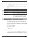
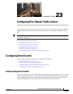
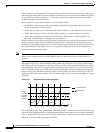
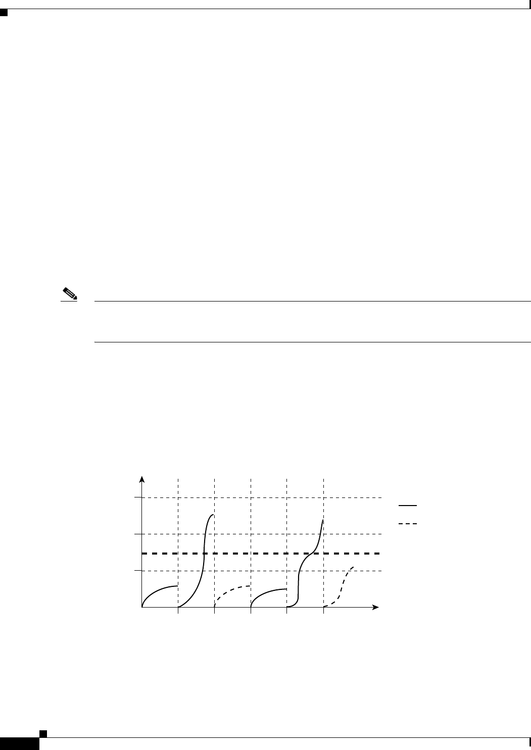
The graph in Figure 23-1 shows broadcast traffic patterns on an interface over a given period of time.
The example can also be applied to multicast and unicast traffic. In this example, the broadcast traffic
being forwarded exceeded the configured threshold between time intervals T1 and T2 and between T4
and T5. When the amount of specified traffic exceeds the threshold, all traffic of that kind is dropped for
the next time period. Therefore, broadcast traffic is blocked during the intervals following T2 and T5.
At the next time interval (for example, T3), if broadcast traffic does not exceed the threshold, it is again
forwarded.
Figure 23-1 Broadcast Storm Control Example
The combination of the storm-control suppression level and the 1-second time interval controls the way
the storm control algorithm works. A higher threshold allows more packets to pass through. A threshold
value of 100 percent means that no limit is placed on the traffic. A value of 0.0 means that all broadcast,
multicast, or unicast traffic on that port is blocked.
Total
number of
broadcast
packets
or bytes
Forwarded traffic
0T1
Threshold
T2 T4 T5
46651
T3 Time
Blocked traffic