


17-9
Catalyst 2960 and 2960-S Switch Software Configuration Guide
OL-8603-09
Chapter 17 Configuring MSTP
Understanding MSTP
MSTP and Switch Stacks
Note Stacking is supported only on Catalyst 2960-S switches running the LAN base image.
A switch stack appears as a single spanning-tree node to the rest of the network, and all stack members
use the same switch ID for a given spanning tree. The switch ID is derived from the MAC address of the
stack master.
If a switch that does not support MSTP is added to a switch stack that does support MSTP or the reverse,
the switch is put into a version mismatch state. If possible, the switch is automatically upgraded or
downgraded to the same version of software that is running on the switch stack.
When a new switch joins the stack, it sets its switch ID to the stack master switch ID. If the newly added
switch has the lowest ID and if the root path cost is the same among all stack members, the newly added
switch becomes the stack root. A topology change occurs if the newly added switch contains a better
root port for the switch stack or a better designated port for the LAN connected to the stack. The newly
added switch causes a topology change in the network if another switch connected to the newly added
switch changes its root port or designated ports.
When a stack member leaves the stack, spanning-tree reconvergence occurs within the stack (and
possibly outside the stack). The remaining stack member with the lowest stack port ID becomes the stack
root.
If the stack master fails or leaves the stack, the stack members elect a new stack master, and all stack
members change their switch IDs of the spanning trees to the new master switch ID.
For more information about switch stacks, see Chapter 7, “Managing Switch Stacks.”
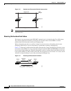
Interoperability with IEEE 802.1D STP
A switch running MSTP supports a built-in protocol migration mechanism that enables it to interoperate
with legacy IEEE 802.1D switches. If this switch receives a legacy IEEE 802.1D configuration BPDU
(a BPDU with the protocol version set to 0), it sends only IEEE 802.1D BPDUs on that port. An MSTP
switch also can detect that a port is at the boundary of a region when it receives a legacy BPDU, an MSTP
BPDU (Version 3) associated with a different region, or an RSTP BPDU (Version 2).
However, the switch does not automatically revert to the MSTP mode if it no longer receives
IEEE 802.1D BPDUs because it cannot detect whether the legacy switch has been removed from the link
unless the legacy switch is the designated switch. A switch might also continue to assign a boundary role
to a port when the switch to which this switch is connected has joined the region. To restart the protocol
migration process (force the renegotiation with neighboring switches), use the clear spanning-tree
detected-protocols privileged EXEC command.
If all the legacy switches on the link are RSTP switches, they can process MSTP BPDUs as if they are
RSTP BPDUs. Therefore, MSTP switches send either a Version 0 configuration and TCN BPDUs or
Version 3 MSTP BPDUs on a boundary port. A boundary port connects to a LAN, the designated switch
of which is either a single spanning-tree switch or a switch with a different MST configuration.