


22-21
Catalyst 2960 and 2960-S Switch Software Configuration Guide
OL-8603-09
Chapter 22 Configuring IGMP Snooping and MVR
Configuring MVR
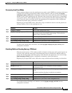
To return the switch to its default settings, use the no mvr [mode | group ip-address | querytime | vlan]
global configuration commands.
This example shows how to enable MVR, configure the group address, set the query time to 1 second
(10 tenths), specify the MVR multicast VLAN as VLAN 22, and set the MVR mode as dynamic:
Switch(config)# mvr
Switch(config)# mvr group 228.1.23.4
Switch(config)# mvr querytime 10
Switch(config)# mvr vlan 22
Switch(config)# mvr mode dynamic
Switch(config)# end
You can use the show mvr members privileged EXEC command to verify the MVR multicast group
addresses on the switch.
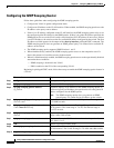
Configuring MVR Interfaces
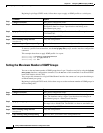
Beginning in privileged EXEC mode, follow these steps to configure Layer 2 MVR interfaces:
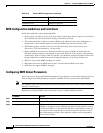
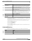
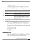
Step 4
mvr querytime value (Optional) Define the maximum time to wait for IGMP report memberships
on a receiver port before removing the port from multicast group membership.
The value is in units of tenths of a second. The range is 1 to 100, and the
default is 5 tenths or one-half second.
Step 5
mvr vlan vlan-id (Optional) Specify the VLAN in which multicast data is received; all source
ports must belong to this VLAN. The VLAN range is 1 to 1001 and 1006 to
4094. The default is VLAN 1.
Step 6
mvr mode {dynamic | compatible} (Optional) Specify the MVR mode of operation:
• dynamic—Allows dynamic MVR membership on source ports.
• compatible—Is compatible with Catalyst 3500 XL and Catalyst 2900 XL
switches and does not support IGMP dynamic joins on source ports.
The default is compatible mode.
Step 7
end Return to privileged EXEC mode.
Step 8
show mvr or show mvr members Verify the configuration.
Step 9
copy running-config
startup-config
(Optional) Save your entries in the configuration file.
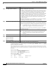
Command Purpose
Command Purpose
Step 1
configure terminal Enter global configuration mode.
Step 2
mvr Enable MVR on the switch.
Step 3
interface interface-id Specify the Layer 2 port to configure, and enter interface configuration
mode.