ARCHITECTURE AND INSTRUCTIONS
to
256
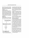
4-byte entries in the table, one for each
interrupt type that can occur in the system.
Each entry
is
a doubleword pointer
(4
bytes)
containing the address of the procedure. The
higher-addressed word of the pointer con-
tains the base address of the segment
containing the procedure. The lower-
addressed word contains the procedure's
offset from the beginning of the segment.
Since each entry
is
four bytes long, the
CPU
can calculate the location of the correct entry
for a given interrupt type by simply multiply-
ing (type*4).
Memory location
FFFFOH, sixteen bytes
from the absolute top of the
8088's address
range
is
the first location from which the
8088
fetches
an
instruction following a sys-
tem
RESET (the activation of the RESET
pin on the
8088
CPU chip, usually
at
the time
system
is
powered up). This memory location
usually contains a jump (JMP) instruction to
the actual beginning
of
the system program
somewhere else in memory.
ORGANIZATION OF THE INSTRUCTION
SET
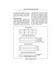
Instructions are described here in six func-
tional groups:
1)
Data transfer
2)
Arithmetic
3) Logic
4)
String manipulation
5)
Control transfer
6)
Processor control
Each of the first three groups mentioned in
the preceding list
is
further subdivided into
an
array of codes that specify whether the
instruction
is
to act upon immediate data,
register
or
memory locations, whether 16-bit
words or 8-bit bytes
are to
be
processed, and
what addressing mode
is
to be employed. All
of
these codes are listed and explained in
detail in this book, but when you are writing
assembly-language programs you do not
have to code each one individually. The con-
2-10
text of your program automatically causes
the assembler to generate the correct code.
There are three general categories of instruc-
tions within each of the three functional
groups mentioned:
I) Register or memory space to or from
register
2)
Immediate data to register
or
memory
3) Accumulator to or from registers, mem-
ory,
or
ports
The details of the syntax of the
8088
instruc-
tion set are described fully in Intel's iAPX
86,
88
assembly language programming manual.
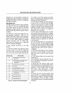
Data Transfer Instructions
Data
transfer instructions are divided into
four classes:
I) General purpose
2)
Accumulator-specific
3) Address-object
4) Flag
N one affect flag setting except
SAHF
and
POPF.
General Purpose Transfers
Four
general purpose data transfer opera-
tions are provided and may be applied to
most operands, though there are specific
exceptions. The general purpose transfers
(except XCHG) are the only operations
which allow a segment register as an operand.
MOV
performs a byte or word transfer from
the source operand to the destination operand.
PUSH decrements the
SP
register by two
and
then transfers a word from the source
operand to the stack element currently
addressed by
SP.
POP
transfers a word operand from the
stack element addressed by the
SP
register to
the destination operand and then increments
SP
by
2.
XCHG
exchanges the byte or word source
operand
with, the destination operand. The
segment registers may not be operands of
XCHG.


