


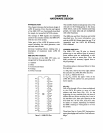

HARDWARE DESIGN
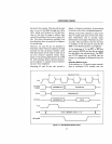
device must tell the
CPU
that the data
transfer
is
not complete and that the machine
cycle must be extended.
It
does this by bring-
ing the
READY
input LOW before the
beginning of
T3.
This forces the
8088
to insert
additional clock cycles (Wait States or Tw's)
between
T3
and T 4.
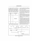
Bus
activity during Tw
is
the same as
T3.
The
address and control signals remain on the
bus, allowing time to complete the
data
transfer. When the selected device has com-
pleted the transfer, it brings the READY pin
RIG
R, allowing the
CPU
to continue from
the Tw states into T
4.
The
CPU
will then latch the data on the bus
during T
4, as it would during a normal
machine cycle. The machine cycle
is
then
terminated in T
4 when the
command
lines
are disabled, and the external device
is
de-
selected. Refer to READY,
see
pg. 3-16, and
the
iAPX 86,
88
User's Manual.
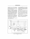
Idle Cycles
The
8088
CPU
only executes a machine cycle
when instructions
or
operands must be trans-
ferred between the
8088
and memory or
I/O
devices. When not executing a machine cycle,
the bus interface executes idle cycles (TJ).
During these idle cycles, the
CPU
continues
to drive status information from the previous
machine cycle on the upper address lines.
If
the previous machine cycle was a write, the
CPU
continues to drive the write data onto
the multiplexed bus until the start
of
the next
machine cycle. If the
CPU
executes idle
cycles following a read cycle, the
CPU
will
not
drive the lower 8 bus lines until the next
machine cycle
is
required.
Because the
CPU
prefetches up to 4 bytes
of
the instruction stream for the internal instruc-
tion queue, the relationship of instruction
fetch and associated operand transfers may
be skewed in time and separated by addi-
tional instruction fetches.
3-8
In general, if a given instruction
is
fetched
into the
8088's internal instruction queue,
several additional instructions may be fetched
before the given instruction
is
removed from
the queue and executed.
If
the. instruction being executed
is
a
jump
or
other control transfer instruction, any instruc-
tions remaining in the queue are discarded
without execution.
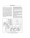
Bus Interface
The bus interface of an iAPX
88
can be struc-
tured in a number of ways. The best configur-
ation for a particular application depends on
system size, and the type of memory, and
va
devices used.
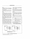
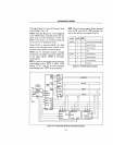
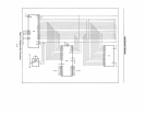
The simplest bus interface for
an
iAPX
88
system uses the "multiplexed bus" configura-
tion. In this system, memory and
I/O
devices
are attached directly to the
8088's multi-
plexed Address/Data
Bus
(Fig.
3-4).
This
configuration
is
ideal for small systems where
simplicity and low component-count are
important.
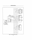
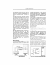
Each device must use ALE to internally latch
the address and separate it from data. There
are, however, certain limitations to this sys-
tem. First, only memory and
I/O
devices
specifically designed to operate on a multi-
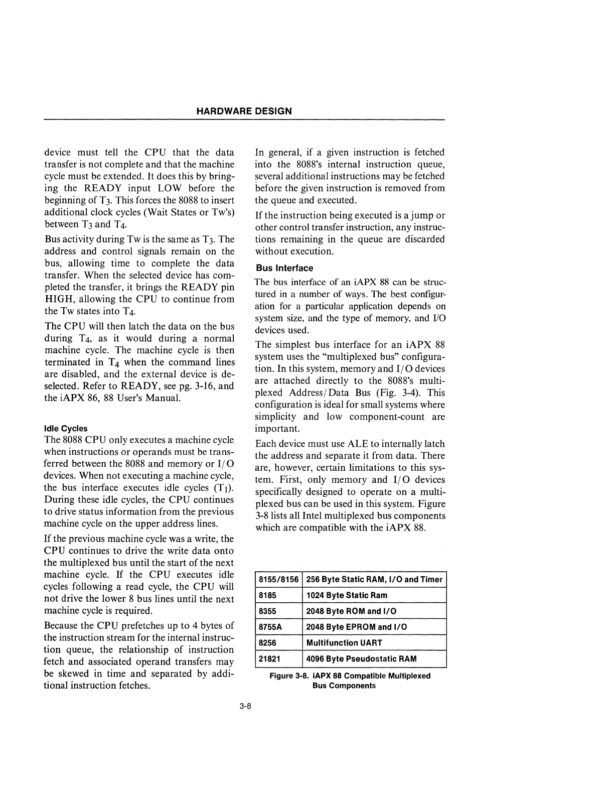
plexed bus can be used in this system. Figure
3-8
lists all Intel multiplexed bus components
which are compatible with the
iAPX
88.
8155/8156 256 Byte Static RAM,
I/O
and Timer
8185
1024 Byte Static
Ram
8355 2048 Byte ROM and
I/O
8755A 2048 Byte EPROM and
I/O
8256 Multifunction UART
21821
4096 Byte Pseudo static
RAM
Figure 3-8. iAPX
88
Compatible Multiplexed
Bus
Components