


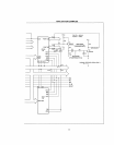
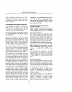

APPLICATION EXAMPLES
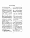
Using a dynamic storage cell, the
21821
includes all the necessary support logic such
as refresh control, arbiter, latches, and multi-
plexers. (Fig.
4-3)
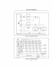
iAPX
88
DEMUL TIPLEXED BUS SYSTEM
In this application example
we
will
look at an
iAPX
88
system which uses
2114
RAMs
connected to a demultiplexed bus, and an
8251
A to implement a serial interface.
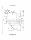
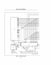
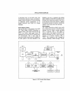
As seen in Figure 4-4, the
8088
CPU receives
its
CLOCK, READY and RESET signals
from the 8284A.
The control software
is
in the 8755A
EPROM. This software contains the "boot-
up"
routine which tells the
CPU
how to get
started when the system
is
reset.
It
might also
contain a small monitor,
an
interpreter such
as TINY BASIC, or some game software.
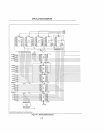
The
8155
provides
256
bytes of RAM,
timer
I counter and
22
110 lines. Both devices
connect directly to the 8088's multiplexed
addressl data bus because they internallly
latch the address when ALE goes
LOW.
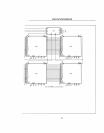
The majority of the system
RAM
is
provided
by two
2ll4s.
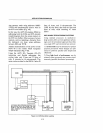
These
1K
x 4 static RAMs do
not internally latch the lower 8-bits of address
as the
8755
and
8155
do.
For
this reason,
an
8282
octal latch
is
used to provide a
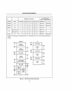
demultip1exed address bus. The
8282
looks
at
the lower eight bits of address
at
the
beginning of each machine cycle, and holds it
on the address bus on the falling edge of ALE.
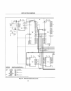
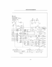
Note that the
2114s
are chip selected, using a
decoded address from the
8205
decoder,
combined with the
DEN
output of the
8088.
The
DEN
delays the chip select until the
system
is
ready for data to
be
driven onto the
data bus.
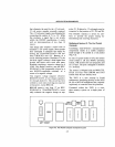
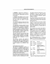
If
this were not done, the 2l14s
would output data onto the data bus shortly
after the address appeared on the bus. This
would cause a problem called
"bus con-
tention", where the
8088
is
driving address
4-10
information on the addressl data bus at the
same time the
2114s
are beginning to drive
data on that same bus
(see
Fig.
4-5).
This
is
prevented by using
DEN
to delay
CS
until
after ALE goes
LOW.
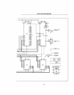
Universal Synchronous/Asynchronous
Receiver/Transmitter
Another important part of this design
is
the
8251A USART. The 8251A
is
a peripheral
device programmed by the
CPU to transmit
and receive serial data.
The
USAR T accepts data characters from
the
CPU in parallel, and then converts the
characters into a serial data stream for
transmission. Simultaneously, the 825lA can
receive serial data streams and convert them
into parallel data characters for the
CPU.
The
8088
and 8251A interface
is
quite simple.
Data travels to and from the 8251A via the
8088's multiplexed address
I data bus. The
RD
and
WR
inputs of the 8251A are driven
directly by the 8088's
RD
and
WR
control
lines.
The Chip select
is
provided by the
8205
address decoder, and address line
AO
tells the
USAR T whether the data bus
is
transmitting
a data character
or
a control I status char-
acter.
Baud/Rate Generation
The rate serial data shifts into and out of the
8251A
is
controlled by the Receiver Clock
(RxC)
and
Transmitter Clock (TxC) inputs.
They are provided by the TIMER
OUT output
from the 8155's 14-bit counter/timer.
A demultiplexed system
is
useful for a
number of applications, including small
control or monitoring systems, dedicated
testing, or games.
The monitor software for the 8755A
is
available through Insite, the INTEL users
library.
It
contains a "bootup" routine,
display
I alter memory and registers, single
step, break point, and other functions.