


ARCHITECTURE AND INSTRUCTIONS
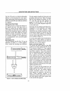
Programs can be dynamically relocated by
changing the segment registers, provided the
program itself does not load or manipulate
the segment
registers;
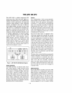
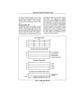
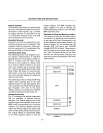
Flag
Register
File
Six flags provide processor status informa-
tion (Fig. 2-2). Five are the
8080/8085 flags
and usually reflect the status of the latest
arithmetic or logical operation. The sixth, an
OVERFLOW flag, reflects a signed overflow
condition.
The
8088
also contains three flags that con-
trol processor operations. These are the
DIRECTION flag, which controls the direc-
tion of the string manipulations; the
INTER~
RUPT
FLAG, which enables or disables
external interrupts; and the
TRAP
flag,
which puts the processor into a single-step
mode for program debugging.
A more detailed discussion of the flags
,follows:
1)
If
AF
(the auxiliary carry flag)
is
set, there
has been a carry out of the low nibble (the
low order 4-bits of a byte) into the high nib-
ble or a borrow from the high nibble into the
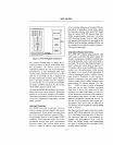
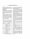
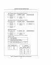
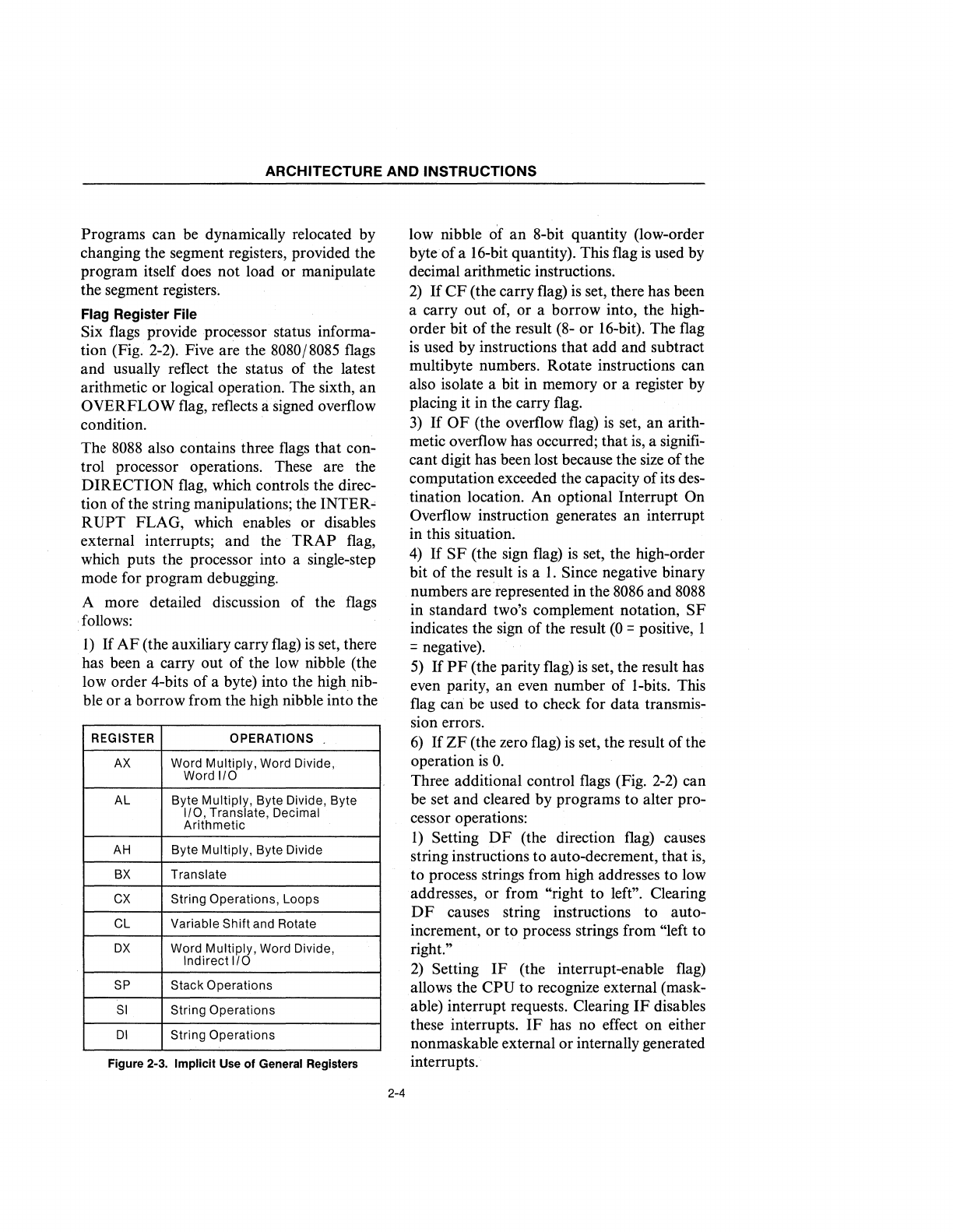
REGISTER OPERATIONS .
AX
Word Multiply, Word Divide,
Word
1/0
AL Byte Multiply, Byte Divide, Byte
1/0, Translate, Decimal
Arithmetic
AH
Byte Multiply, Byte Divide
BX
Translate
CX
String Operations, Loops
CL Variable Shift and Rotate
OX
Word Multiply, Word Divide,
Indirect
I/O
SP
Stack Operations
SI
String Operations
01
String Operations
Figure 2-3. Implicit Use
of
General Registers
2-4
low nibble of
an
8-bit quantity (low-order
byte of a 16-bit quantity). This flag
is
used by
decimal arithmetic instructions.
2)
If
CF
(the carry flag)
is
set, there has been
a carry out of, or a borrow into, the high-
order bit of the result (8- or 16-bit). The flag
is
used by instructions that add and subtract
multi byte numbers. Rotate instructions can
also isolate a bit in memory or a register
by
placing it in the carry flag.
3)
If
OF
(the overflow flag)
is
set, an arith-
metic overflow has occurred; that
is,
a signifi-
cant digit has been lost because the
size
of the
computation exceeded the capacity of its des-
tination location. An optional Interrupt
On
Overflow instruction generates an interrupt
in this situation.
4)
If
SF
(the sign flag)
is
set, the high-order
bit
of
the result
is
a
1.
Since negative binary
numbers are represented in the 8086 and
8088
in standard two's complement notation,
SF
indicates the sign of the result
(0
= positive, 1
= negative).
5)
If
PF
(the parity flag)
is
set, the result has
even parity, an even number of I-bits. This
flag
can be used to check for data transmis-
sion errors.
6)
If
ZF
(the zero flag)
is
set, the result of the
operation
is
o.
Three additional control flags (Fig.
2-2)
can
be set and cleared by programs to alter pro-
cessor operations:
1)
Setting
DF
(the direction flag) causes
string instructions to auto-decrement, that is,
to process strings from high addresses to low
addresses, or from
"right to left". Clearing
DF
causes string instructions to auto-
increment, or to process strings from
'~left
to
right."
2)
Setting
IF
(the interrupt-enable flag)
allows the
CPU
to recognize external (mask-
able) interrupt requests. Clearing
IF
disables
these interrupts.
IF
has no effect on either
nonmaskable external or internally generated
interrupts.