


CHAPTER 2
THE iAPX
88
ARCHITECTURE AND INSTRUCTIONS
INTRODUCTION
This chapter describes the programmer's
architecture of the
8088
CPU. The pro-
gramming model
is
presented first, including
the memory and
Ij
0 port organizations and
the
CPU
registers. The addressing modes are
described next, followed by
an
introduction
to the instruction set and the iAPX
88
assembly language. The iAPX
88
instruction
set reference pages that describe each instruc-
tion in detail conclude the chapter.
iAPX
88
ARCHITECTURE
The iAPX
88
processor architecture com-
prises a memory structure, a register structure,
an
instruction set, and a set of addressing
modes. The
8088
CPU can access up to one
million bytes
of
memory and up to 64K inputj
output ports.
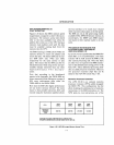
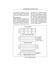
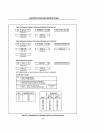
The
8088
has three register
files:
1)
data registers to hold intermediate results;
2)
pointer and index registers to reference
within specified portions of memory;
3)
segment registers used to specify these por-
tions of memory.
The
8088
has nine flags that are used to
record the state of the processor and to con-
trol its operations.
The
8088
instruction set and addressing
modes are richer and more symmetric than
the
8080. And the
8088
external interface,
providing such things as interrupts, multip-
rocessor synchronization, and resource shar-
ing, exceeds the facilities provided in the
8080, the
8085,
or the
Z80®.
Memory Structure
The
8088
inputj output space and memory
space are treated in parallel and are collec-
tively called the memory structure. Code and
data reside in the memory space while (non-
memory-mapped) peripheral devices reside in
the
Ij
0 space.
Z80 is a registered trademark
of
Zilog Corp.
2-1
Memory Space
The memory in
aniAPX
88
system
is
a
sequence of up to one million bytes (a 64-fold
increase over the
8080).
An
8088
word
is
any
two consecutive bytes in memory. Like the
8080,
words
are
stored
in
memory with the
most significant byte at the higher memory
address.
The one-megabyte memory can be conceived
of as
an
arbitrary
number
of
segments, each
containing at most 64K bytes. The starting
address
of
each segment
is
evenly divisible by
16
(the four least significant address bits are
0).
At any moment, the program can imme-
diately access the contents of four such
segments:
1)
Current code segment
2)
Current data segment
3)
Current stack segment
4)
Current extra segment
Each
of
these segments can be identified by
placing the
16
most significant bits
of
the
segment starting address into one
of
the four
16-bit segment registers.
By
contrast, the
8080
memory structure
is
simply the
8088
memory structure with all four
of
the current
segments starting
at
O.
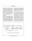
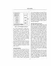
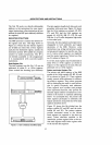
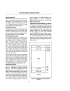
An
8088
instruction can refer to bytes or
words within a segment by using a 16-bit
offset address. The processor constructs the
20-bit byte or word address automatically by
adding the 16-bit offset address (also called
the logical address) to the contents of a 16-bit
segment register, with four low-order zeros
appended (Fig.
2-1).
Input/Output Space
The
8088
Ij
0 space consists
of
64K ports (a
256-fold increase over the
8080). Ports are
addressed the same way
as
memory except
there are no port segment registers.
That
is,
all ports are considered to be in one segment.
Like memory, ports may be
8-
or 16-bits in
SIze.