


ARCHITECTURE AND INSTRUCTIONS
The first
256
ports are directly addressable
(address in the instruction) by some input/
output instructions, other instructions let you
address the total64K ports indirectly (address
in a register).
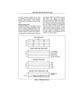
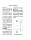
REGISTER STRUCTURE
The
8088
processor contains the thirteen
16-
bit registers and nine I-bit
flags
shown in
Figure
2-2.
Notice that the thirteen registers
are divided into three files of four registers
each plus the thirteenth register, namely the
instruction pointer
(IP) (called the program
counter in earlier processors). The
IP
is
not directly accessible to the. programmer;
it
is
manipulated
with
control-transfer
instructions.
Data Register File
The data registers (top
file
Fig.
2-2)
can be
addressed as either
8-
or 16-bit registers.
(Note vertical line showing byte divisions).
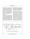
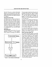
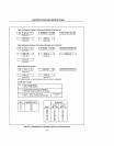
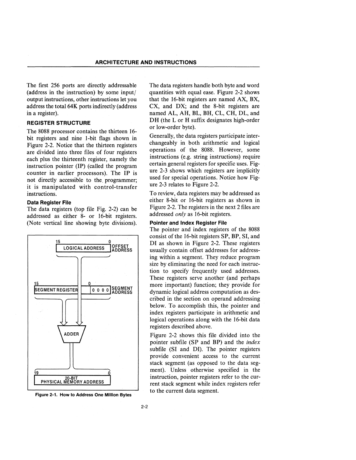
15
0
I
LO
I
OFFSET
GICAL
ADDRESS
ADDRESS
15
EGMENT
REGISTE
SEGMENT
1-....1....
__
....1
ADDRESS
19
G
I
20-BIT
I
PHYSICAL
MEMORY
ADDRESS
Figure 2-1. How to Address One Million Bytes
2-2
The data registers handle both byte and word
quantities with equal ease. Figure
2-2
shows
that the 16-bit registers are named AX, BX,
CX, and DX; and the 8-bit registers are
named AL, AH, BL, BH, CL, CH, DL, and
DH
(the
Lor
H suffix designates high-order
or
low-order byte).
Generally, the data registers participate inter-
changeably in both arithmetic and logical
operations of the
8088.
However, some
instructions (e.g. string instructions) require
certain general registers for specific uses. Fig-
ure
2-3
shows which registers are implicitly
used for special operations. Notice how Fig-
ure
2-3
relates to Figure
2-2.
To review, data registers may be addressed as
either 8-bit or 16-bit registers as shown in
Figure
2-2.
The registers in the next 2
files
are
addressed only as 16-bit registers.
Pointer and Index Register File
The pointer and index registers of the
8088
consist
ofthe
16-bit registers SP, BP, SI, and
DI
as shown in Figure
2-2.
These registers
usually contain offset addresses for address-
ing within a segment. They reduce program
size by eliminating the need for each instruc-
tion to specify frequently used addresses.
These registers serve another (and perhaps
more important) function; they provide for
dynamic logical address computation as des-
cribed in the section on operand addressing
below. To accomplish this, the pointer and
index registers participate in arithmetic and
logical operations along with the 16-bit data
registers described above.
Figure 2-2 shows this
file
divided into the
pointer subfile
(SP
and BP) and the index
subfile (SI and DI). The pointer registers
provide convenient access to the current
stack segment (as opposed to the data seg-
ment). Unless otherwise specified in the
instruction, pointer registers refer to the cur-
rent stack segment while index registers refer
to the current data segment.