


THE
iAPX
188
CPU
The iAPX
188
is a highly integrated
CPU
board-on-a-chip. Most previous highly in-
tegrated microprocessors were optimized for
real-time control applications and supported
relatively small programs in their integrated
memory. Examples
of
this type
of
chip are
Intel's
8048
and
8051
and Zilog's Z8. The iAPX
188,
however, is optimized for computing ap-
plications.
It
retains all the bus interface capa-
bilities
of
multi-chip microprocessors, yet it
integrates common peripheral functions used
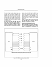
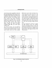
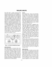
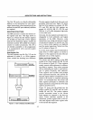
in computer applications. As shown in Figure
1,
the integrated functions on the iAPX
188
include the CPU, clock generator, timers,
DMA channels, interrupt controller, I/O and
memory chip selects, ready generation, and
added
internal
registers
to
control
these
devices (Figure
2).
The iAPX
188
can replace
15-20
of
the most common chips found in a
typical microcomputer system.
Figure 1. iAPX 188 CPU (80188) Block Diagram
Clock Generator
The
80188
provides an internal clock oscil-
lator, which requires a single external crystal
or
TTL-level frequency source. The system
clock output is a standard 8 MHz,
50%
duty
cycle clock at half the
16
MHz crystal fre-
quency. This output can be used to drive the
clock inputs
of
other system components and
hence makes additional
clock
generation
devices unnecessary. Synchronous and asyn-
chronous ready inputs are supplied for flexible
peripheral-device synchronization.
Timers
Two
independent
16-bit
programmable
timer/counters are provided to count
or
time
external events and generate nonrepetitive
waveforms. A
third
16-bit programmable
timer, not connected externally,
is
useful for
implementing time delays and as a prescaler
for the two externally connected timers. The
iAPX
188
integrated timers are very flexible
and can be configured to time/ count a variety
of
distributed I/O activities.
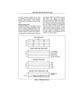
Each
of
the three timers is equipped with a
16-bit timer register that contains the current
value
of
the timer.
It
can be read or written at
any time, independent
of
whether the timer
is
---f running. Each timer
is
also equipped with a
16-bit count register containing the maximum
value the timer will reach. In addition, the two
externally
connected
timers
each
have a
second 16-bit count register which enables the
timers to alternate their count between two
different max count values as programmed by
the user. When a terminal count
is
reached, an
interrupt may be generated, and the timer
value
is
reset to zero.
The timers have several flexible
program~able
modes
of
operation.
All
three timers can be
!set
to halt
or
continue on a terminal count value,
so no external event
or
device need wait for a
timer reset. The two externally connected
timers can select between internal and exter-
nal clocks, alternate between max count regis-
ters
or
use only one, and be set to retrigger on
external events.
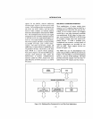
/DMA
Channels
1-20
The on-chip DMA controller unit in the iAPX
188
contains two
independent
high-speed
DMA channels. DMA transfers can occur be-
tween memory and I/O spaces (i.e., M-I/O)
or
within the same space (i.e.,
M-M,
I/O-I/O).
The
latter
feature allows
liD
devices and
memory buffers to be freely located anywhere
in
the
distributed
system.
For
example,
memory-mapped I/O can be handled without