HARDWARE DESIGN
If
a high-accuracy frequency source, externally-
variable frequency source,
or
a common
source
for
driving multiple 8284A's
is
desired,
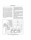
the External Frequency Input (EFI) of the
8284A can be selected by strapping the F /
C
input
HIGH
through a pull-up resistor
(-
IK
ohms). The external frequency source should
be
TTL
compatible, have a
50%
duty cycle,
and oscillate
at
3 times the desired
CPU
operating frequency.
The 8284A has several other functions, includ-
ing
RESET
and
READY
generation (see pg.
3-16).
For
complete details on
iAPX
88
clock
generation, refer to the iAPX 88/lO
and
8284A data sheets.
Reset
The
8088
RESET
line provides
an
orderly
way to start or restart
an
iAPX
88
system.
When the processor detects the positive-
going edge of a pulse on RESET, it
terminates all activities until the signal goes
LOW,
at
which time the internal
CPU
regis-
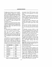
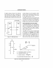
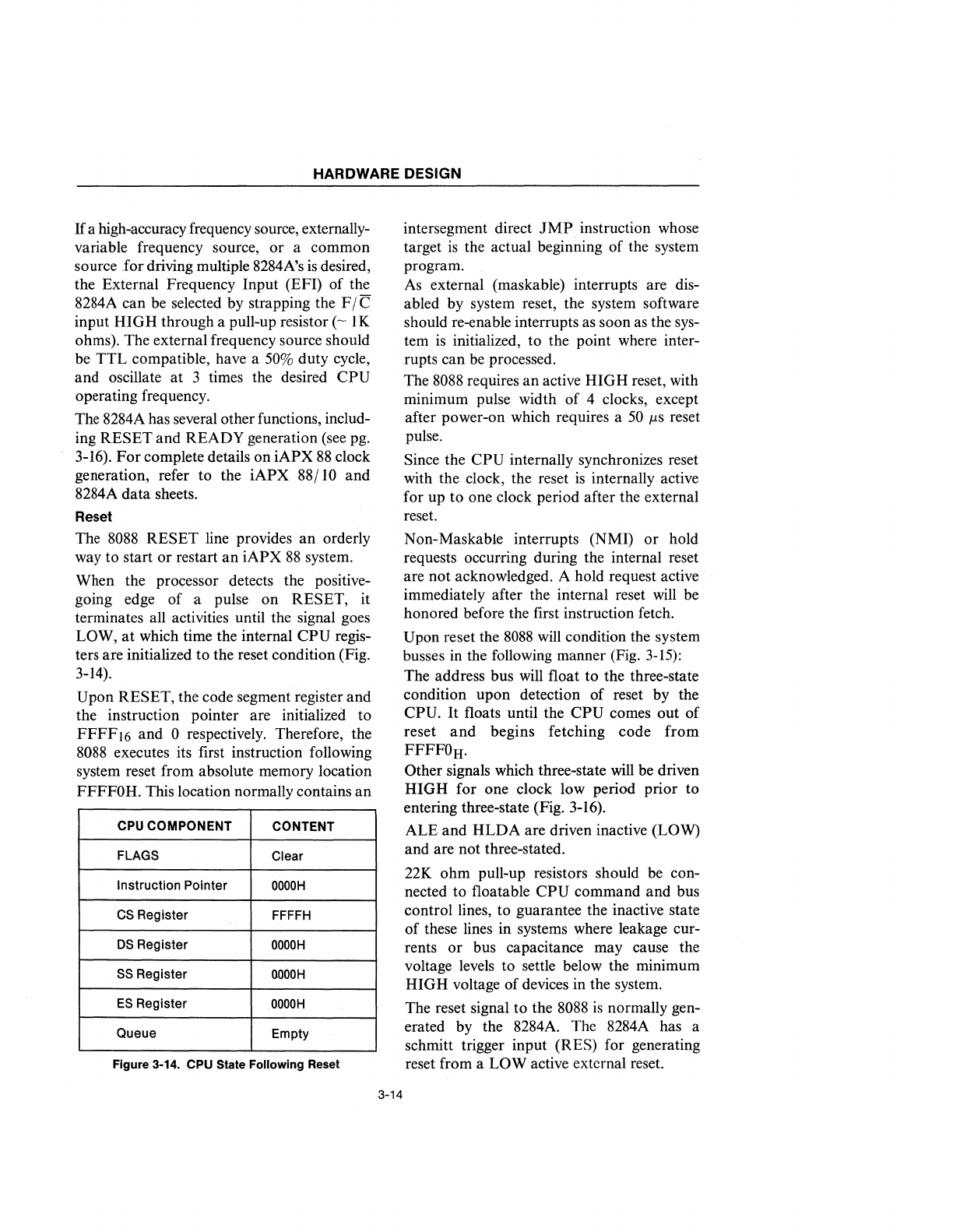
ters are initialized to the reset condition (Fig.
3-14).
Upon RESET, the code segment register and
the instruction pointer are initialized to
FFFF16 and
0 respectively. Therefore, the
8088
executes its first instruction following
system reset from absolute memory location
FFFFOH. This location normally contains
an
CPU
COMPONENT
CONTENT
FLAGS
Clear
Instruction
Pointer
OOOOH
CS
Register
FFFFH
DS
Register
OOOOH
SS
Register
OOOOH
ES
Register
OOOOH
Queue
Empty
Figure 3-14. CPU State Following Reset
3-14
intersegment direct
JMP
instruction whose
target
is
the actual beginning of the system
program.
As
external (maskable) interrupts are dis-
abled by system reset, the system software
should re-enable interrupts as soon
as
the sys-
tem
is
initialized, to the point where inter-
rupts can
be
processed.
The
8088
requires
an
active
HIGH
reset, with
minimum pulse width of 4 clocks, except
after power-on which requires a
50
jlS
reset
pulse.
Since the
CPU
internally synchronizes reset
with the clock, the reset
is
internally active
for up to one clock period after the external
reset.
Non-Maskable interrupts (NMI) or hold
requests occurring during the internal reset
are not acknowledged. A hold request active
immediately after the internal reset will be
honored before the first instruction fetch.
Upon reset the
8088
will condition the system
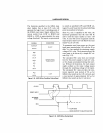
busses in the following manner (Fig.
3-15):
The address bus will float to the three-state
condition upon detection
of
reset by the
CPU.
It
floats until the
CPU
comes out of
reset
and
begins fetching code
from
FFFFOH·
Other
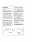
signals which three-state will be driven
HIGH
for one clock low period prior to
entering three-state (Fig.
3-16).
ALE
and
HLDA
are driven inactive (LOW)
and are not three-stated.
22K ohm pull-up resistors should be con-
nected to floatable
CPU
command and bus
control lines, to guarantee the inactive state
of
these lines in systems where leakage cur-
rents
or
bus capacitance may cause the
voltage levels to settle below the minimum
HIGH voltage of devices in the system.
The reset signal to the
8088
is
normally gen-
erated by the 8284A. The 8284A has a
schmitt trigger input (RES) for generating
reset from a
LOW active external reset.


