


HARDWARE DESIGN
SINGLE-STEP EXECUTION
If
the
trap
flag (TF)
is
set, the
CPU
automat-
ically generates a type 1 interrupt following
every instruction. Single-step execution
is
a
powerful debugging tool.
If
the overflow flag (OF)
is
set,
an
INTO
(interrupt on overflow) instruction generates
a type 4 interrupt immediately upon comple-
tion of its execution.
All internal interrupts,
INT
n, INTO, divide
error, and single-step share these character-
istics:
1)
The interrupt type code
is
either contained
in the instruction or
is
predefined.
2)
No INTA machine cycles are run.
3)
Internal interrupts cannot be disabled,
except for single-step.
4)
Any internal interrupt (except single-step)
has higher priority than any external inter-
rupt (Fig. 3-26).
If
interrupt requests arrive
on
NMI
and/
or
INTR
during execution of
an
instruction that causes
an
internal inter-
rupt (e.g., divide error), the internal interrupt
is
processed first.
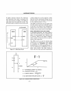
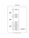
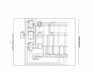
INTERRUPT VECTOR TABLE
The interrupt vector table
is
the link between
an
interrupt type code and the procedure
designated to service interrupts associated
with that code (Fig. 3-25).
The interrupt vector table occupies up to the
first 1 K bytes of low memory. There may be
up to
256
entries in that table, one for each
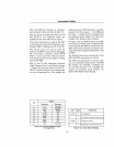
INTERRUPT PRIORITIES
Divide error, INT
n,
INTO
highest
NMI
INTR
Sing Ie-step
lowest
Figure 3-26. Interrupt Priorities
3-23
interrupt type that can occur in the system.
Each entry in the table
is
a double word poin-
ter containing the address of the procedure
that
is
to service interrupts of that type.
The higher-addressed word of the pointer
contains the base address of the code segment
containing the procedure. The lower-
addressed word contains the procedure's
offset from the beginning of the segment.
These two word pointers will
be
placed in the
CS and
IP
registers, respectively, to cause the
CPU
to execute the interrupt service routine.
Since each entry
is
four bytes long, the
CPU
can calculate the location of the correspond-
ing entry for a given interrupt type by simply
multiplying
(type.
4).
Unused space
at
the high end of the interrupt
vector table may be used for other purposes.
The dedicated and reserved portions
of
the
interrupt pointer table (locations
OH-
7FH), however, should
not
be
used for any
other purpose, to insure proper operation
and compatibility with future Intel hardware
and software products.
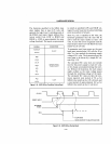
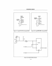
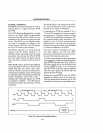
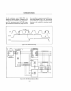
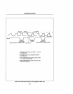
INTERRUPT ACKNOWLEDGE SEQUENCE
When a mask able interrupt
is
acknowledged,
the
CPU
executes two interrupt acknowledge
machine cycles (Fig. 3-24). The
CPU
will
not
recognize a hold request from another bus
master until the full interrupt acknowledge
sequence
is
completed.
During the first machine cycle, the
CPU
floats the address/
data
bus and activates the
INT A (Interrupt Acknowledge) command
output during states
T2
through
T4.
During the second machine cycle, the
CPU
again activates its
INT
A command output.
The external interrupt system (e.g.,
an
Intel®
8259A Programmable Interrupt Controller)
responds to this by placing a byte
on
the
data
bus that identifies the interrupt source, the
vector type. This byte
is
read by the
CPU,
multiplied by four, and used as a pointer into
the interrupt vector table.