


HARDWARE DESIGN
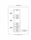
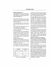
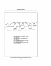
Pins with different functions in mmlmum
and maximum modes are listed in Fig.
3-31.
Pins 26,
27
and
28,
which were DEN,
DT
j R
and
IOjM
in the minimum mode, are
replaced by the status lines
SO,
S 1 and
S2.
These three status lines are used by the
8288
to produce seven bus control functions, ena-
bling the
8088
to redefine pins
24,
25
and
29.
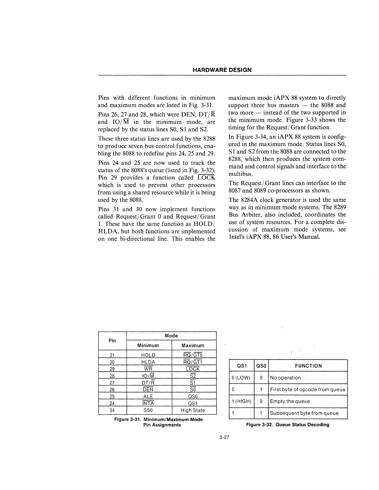
Pins 24 and
25
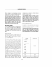
are now used to track the
status of the 8088's queue (listed in Fig. 3-32).
Pin
29
provides a function called LOCK
which
is
used to prevent other processors
from using a shared resource while it
is
being
used by the
8088.
Pins
31
and
30
now implement functions
called Requestj Grant
0 and Requestj Grant
1.
These have the same function
as
HOLDj
HLDA, but both functions are implemented
on one bi-directional line. This enables the
Mode
Pin
31
30
29
28
27
26
25
24
34
Minimum
Maximum
HOLD
RO/GTO
HLDA RO/GT1
WR
LOCK
101M
S2
DT/R
S1
DEN
SO
ALE
OSO
INTA
OS1
SSO
High State
Figure 3-31. Minimum/Maximum Mode
Pin ASSignments
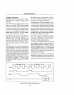
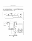
maximum mode
iAPX
88
system to directly
support three bus masters - the
8088
and
two more - instead of the two supported in
the minimum mode. Figure
3-33
shows the
timing for the Requestj Grant function.
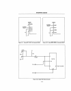
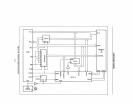
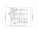
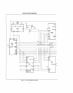
In Figure 3-34,
an
iAPX
88
system
is
config-
ured in the maximum mode. Status lines
SO,
S 1 and S2 from the
8088
are connected to the
8288, which then produces the system com-
mand and control signals and interface
to
the
multibus.
The Requestj Grant lines can interface to the
8087
and
8089
co-processors
as
shown.
The 8284A clock generator
is
used the same
way
as
in minimum mode systems. The 8289
Bus Arbiter, also included, coordinates the
use
of
system resources.
For
a complete dis-
cussion of maximum mode systems,
see
Intel's iAPX
88,
86
User's Manual.
OS1
osa
FUNCTION
O(LOW)
0
No
operation
0 1 First
byte
of
opcode
from
queue
1 (HIGH)
0
Empty the
queue
1 1
Subsequent
byte from
queue
Figure 3-32. Queue Status Decoding
3-27