T400 Ozone Analyzer Operator’s Manual Setup Menu
95
5.4.1.2. Analog Output Ranges for O
3
Concentration
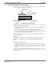
The analyzer has two active analog output signals related to O
3
concentration that are
accessible through a connector on the rear panel.
Not Used
A
NALOG OU
T
A1 A2 A3 A4
+ - + - + - + -
O
3
concentration
outputs
HIG
H
range when DUAL
mode is selected
Test Channel
See Section
7.4.6
LOW range when DUAL
mode is selected
Figure 5-1: Analog Output Connector Pin Out
The A1 and A2 channels output a signal that is proportional to the O
3
concentration of
the sample gas. They can be configured:
With independent reporting ranges reporting a “single” output signal (SNGL Mode,
see Section 5.4.1.3)
to be operate
d completely independently (DUAL Mode, see Section 5.4.1.4).
Or to automa
tically switch between the two ranges dynamically as the concentration
value fluctuates (AUTO modes, see Section 5.4.1.5).
The user can set the units of measure, measure span and signal scale of each output in a
variety of combinations.
EXAMPLE:
A1 OUTPUT: Output Signal = 0-5 VDC representing 0-1000 ppb concentration values
A2 OUTPUT: Output Signal = 0 – 10 VDC representing 0-500 ppb concentration
values.
Both the A1 and A2 outputs can be:
Configured full scale outputs of: 0 - 0.1 VDC; 0 - 1VDC; 0 - 5VDC or; 0 - 10VDC.
Equipped with optional 0-20 mADC current loop drivers (OPT 41, see Section
3.3.1.4) and configured for any current output within that range (e.g. 0-20, 2-2
0, 4-
20, etc.).
The user may also add a signal offset independently to each output (see Section 5.10.1.8)
to match the electronic input requirements of the recorder or data logger to which the
output is connected.
06870C DCN6332


