Setup Menu T400 Ozone Analyzer Operator’s Manual
120
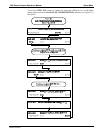
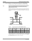
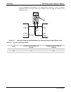
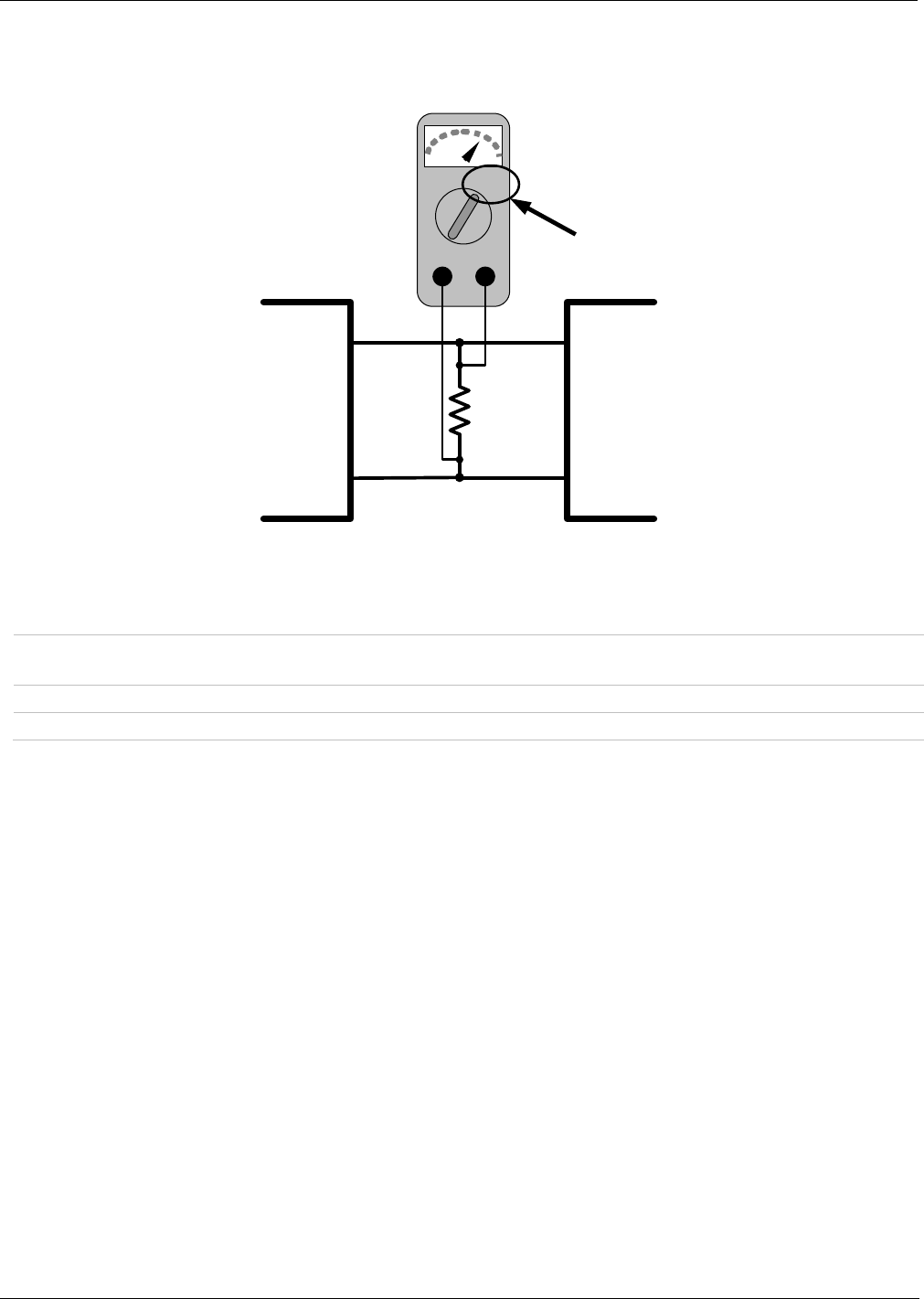
for pin assignments and diagram of the analog output connector). Using a voltmeter
connected across the resistor follow the procedure above but adjust the output for the
following values:
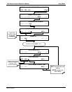
V
+DC Gnd
Recording
Device
V IN +
V IN -
ANALYZER
V OUT +
V OUT -
250 Ω
Volt
Meter
Figure 5-6: Alternative Setup Using 250Ω Resistor for Checking Current Output Signal Levels
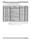
Table 5-6: Current Loop Output Check
% FS
Voltage across Resistor for
2-20 mA
Voltage across Resistor for
4-20 mA
0 0.5 VDC 1 VDC
100 5.0 5.0
06870C DCN6332


