Troubleshooting & Service T400 Ozone Analyzer Operator’s Manual
264
12.7.8.2. A/D Functions
The simplest method to check the operation of the A-to-D converter on the motherboard
is to use the Signal I/O function under the DIAG menu to check the two A/D reference
voltages and input signals that can be easily measured with a voltmeter.
1. Use the Signal I/O function (See Section 12.1.3 and Appendix A) to view the value
of REF_4096_MV and REF_GND.
If both are within 3 mV of nominal (4096 and 0), and are stable, ±0.5 mV then
the basic A/D is functioning properly. If not then the motherboard is bad.
2. Choose a parameter in the Signal I/O function such as PHOTO_LAMP_DRIVE or
SAMPLE_FLOW.
Compare these voltages at their origin (see the interconnect drawing and
interconnect list in Appendix D) with the voltage displayed through the signal I/O
function.
If the wiring is intact but there is a large difference between the measured and
displayed voltage (±10 mV) then the motherboard is bad.
12.7.8.3. Status Outputs
To test the status output electronics:
1. Connect a jumper between the “D“pin and the “” pin on the status output
connector.
2. Connect a 1000 ohm resistor between the “+” pin and the pin for the status output
that is being tested.
3. Connect a voltmeter between the “” pin and the pin of the output being tested (see
table below).
4. Under the DIAG SIGNAL I/O menu (See Section12.1.3), scroll through the inputs
and outp
u
ts until you get to the output in question.
5. Alternately, turn on and off the output noting the voltage on the voltmeter.
It should vary between 0 volts for ON and 5 volts for OFF.
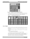
Table 12-10: Status Outputs Check
PIN (LEFT TO RIGHT) STATUS
1
ST_SYSTEM_OK
2
ST_CONC_VALID
3
ST_HIGH_RANGE
4
ST_ZERO_CAL
5
ST_SPAN_CAL
6
ST_DIAGMODE
7
ST_FLOW_ALARM
8
ST_PRESS_ALARM
06870C DCN6332


