Teledyne API – Model T400 Photometric Ozone Analyzer Getting Started
75
INSTRUMENT CHASSIS
SAMPLE
PRESSURE
SENSOR
O
3
FLOW
SENSOR
Sample Gas
Flow Control
O
3
Scrubber
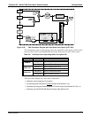
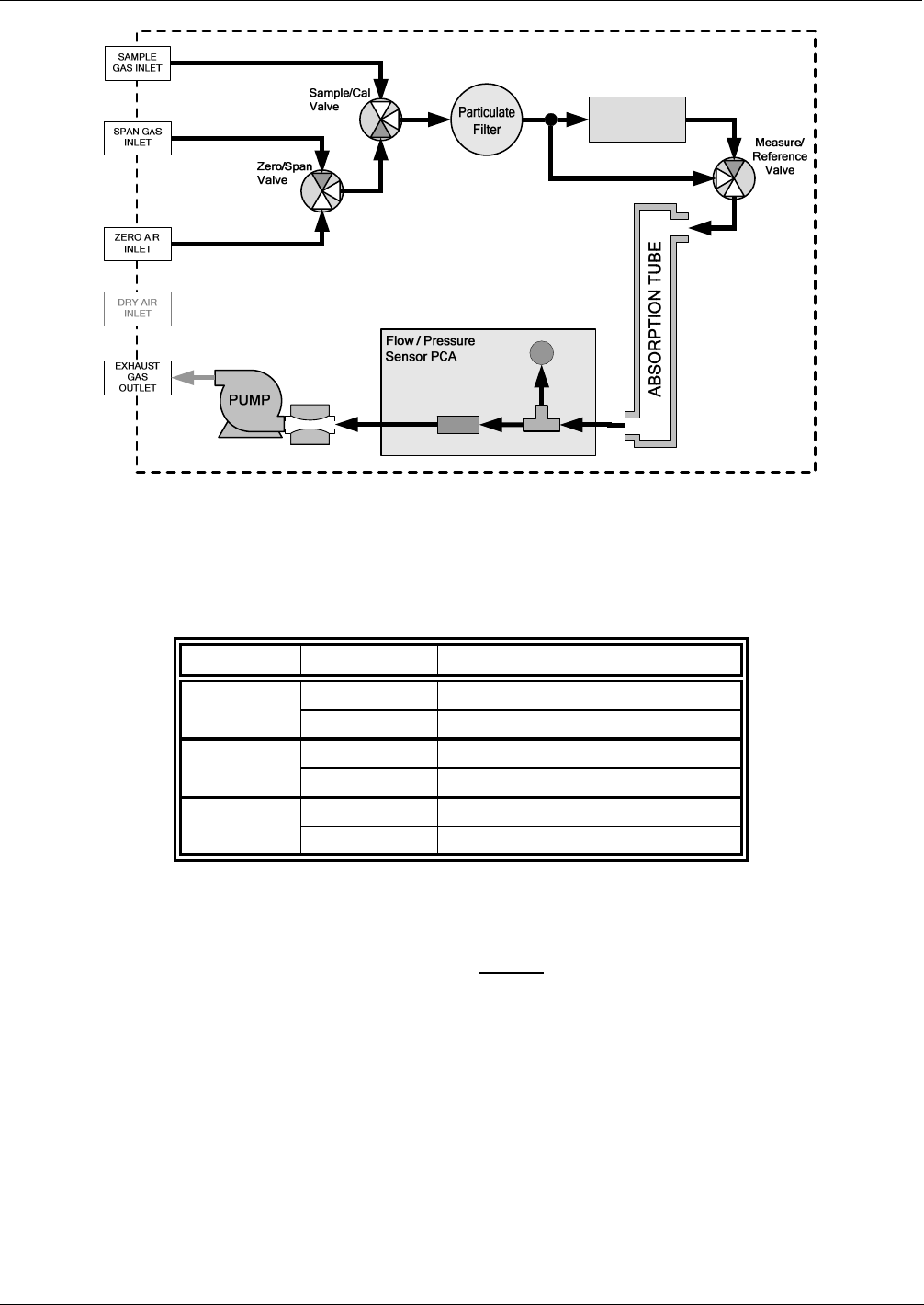
Figure 3-22: T400 Pneumatic Diagram with Zero/Span Valve Option (OPT-50A)
The instrument’s zero air and span gas flow rate required for this option is 800 cc/min,
however, the US EPA recommends that the cal gas flow rate be at least 1600 cc/min.
Table 3-9: Zero/Span Valve Operating States for Option 50A
Mode Valve Condition
Sample/Cal Open to SAMPLE inlet
SAMPLE
Zero/Span Open to ZERO AIR inlet
Sample/Cal Open to ZERO/SPAN Valve
ZERO CAL
Zero/Span Open to ZERO AIR inlet
Sample/Cal Open to ZERO/SPAN Valve
SPAN CAL
Zero/Span Open to SPAN GAS inlet
The state of the Sample/Cal valves can be controlled:
Manually via the analyzer’s front panel;
By activating the instrument’s AutoCal
feature (See Section 9.4);
Remotely by using the External Digital I/O Control Inputs (See Section 9.3.3.3), or;
Remotely via the RS-2
32/485 Serial I/O ports (See Section 8.2).
06870C DCN6332


