


Troubleshooting & Service T400 Ozone Analyzer Operator’s Manual
262
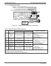
12.7.7. PHOTOMETER PRESSURE /FLOW SENSOR ASSEMBLY
This assembly is only present in analyzers with O
3
generator and/or photometer options
installed. The pressure/flow sensor PCA, located at the rear of the instrument between
the photometer and the pump (see Figure 3-5) can be checked with a Voltmeter. The
following procedure assu
mes that the wiring is intact and that the motherboard as well as
the power supplies are operating properly:
BASIC PCA OPERATION:
Measure the voltage across C1 it should be 5 VDC ± 0.25 VDC. If not then the
board is bad
Measure the voltage between TP2 and TP1 C1 it should be 10 VDC ± 0.25 VDC. If
not then the board is bad.
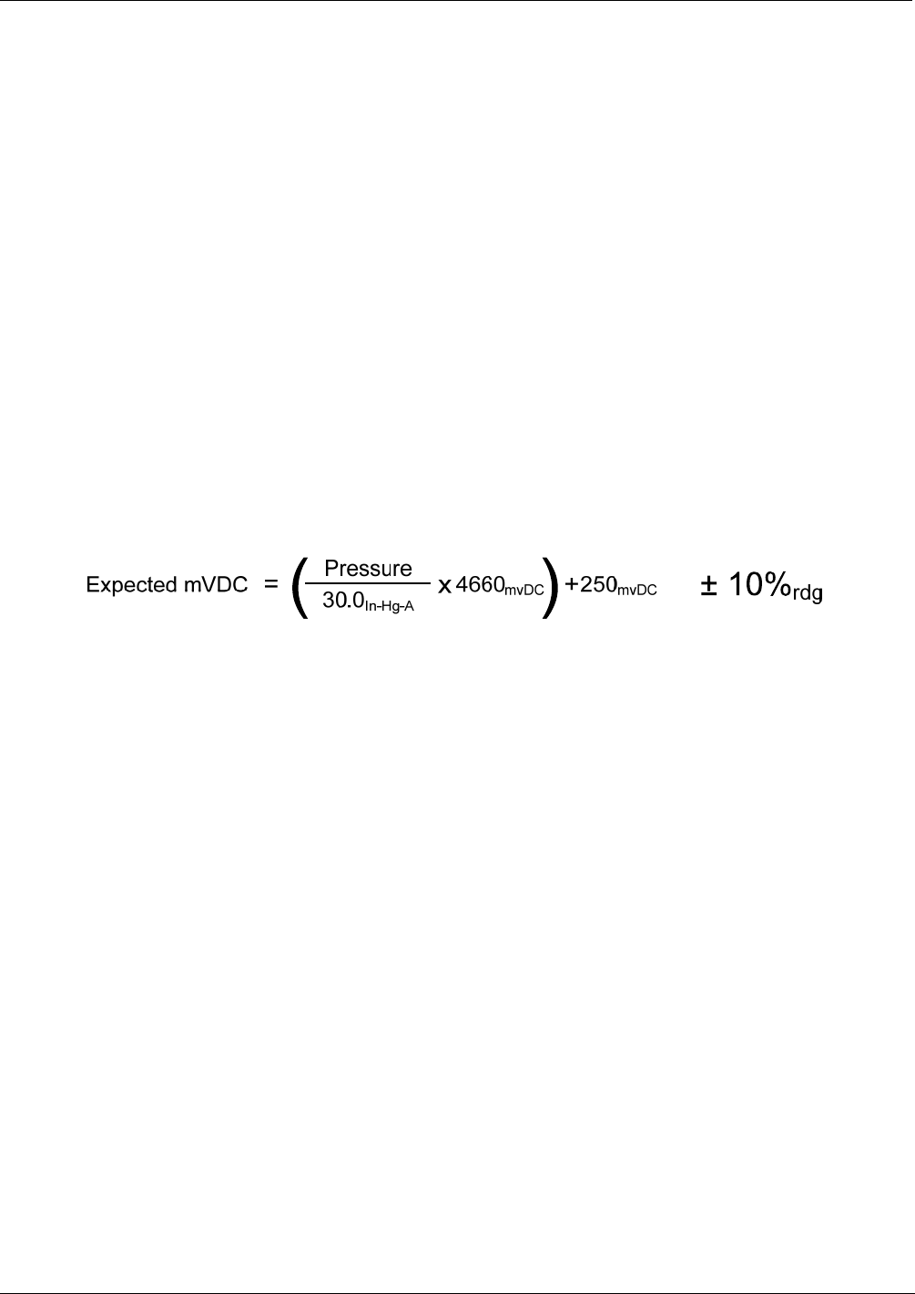
PHOTOMETER PRESSURE SENSOR:
1. Measure the pressure on the inlet side of S1 with an external pressure meter.
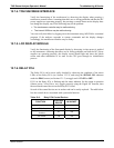
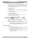
1. Measure the voltage across TP4 and TP1.
The expected value for this signal should be:
EXAMPLE: If the measured pressure is 20 In-Hg-A, the expected voltage level between
TP4 and TP1 would be between 2870 mVDC and 3510 mVDC.
EXAMPLE: If the measured pressure is 25 In-Hg-A, the expected voltage level between
TP4 and TP1 would be between 3533 mVDC and 4318 mVDC.
If this voltage is out of range, then either pressure transducer S1 is bad, the
board is bad or there is a pneumatic failure preventing the pressure transducer
from sensing the absorption cell pressure properly.
PHOTOMETER FLOW SENSOR
Measure the voltage across TP3 and TP1.
With proper flow (800 cc
3
/min through the photometer), this should be
approximately 4.5V (this voltage will vary with altitude).
With flow stopped (photometer inlet disconnected or pump turned OFF) the
voltage should be approximately 1V.
If the voltage is incorrect, the flow sensor S3 is bad, the board is bad or there is
a leak upstream of the sensor.
06870C DCN6332