T400 Ozone Analyzer Operator’s Manual Setup Menu
107
5.8. SETUP VARS: VARIABLES SETUP AND DEFINITION
The T400 has several-user adjustable software variables, which define certain
operational parameters. Usually, these variables are automatically set by the
instrument’s firmware, but can be manually re-defined using the VARS menu.
The following table lists all variables that are available within the 101 password
protected level. See Appendix A2 for a detailed listing of all of the T400 variables that
are accessible through the remote interface.
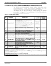
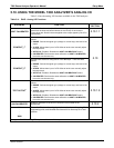
Table 5-2: Variable Names (VARS)
NO. VARIABLE DESCRIPTION
ALLOWED
VALUES
VARS
DEFAULT
VALUES
0
DAS_HOLD_OFF
Changes the Internal Data Acquisition System
(DAS) HOLDOFF timer:
No data is stored in the DAS channels during
situations when the software considers the data to
be questionable such as during warm up of just
after the instrument returns from one of its
calibration mode to SAMPLE Mode.
May be set for
intervals
between
0.5 – 20 min
15 min.
1
CONC_PRECISION
Allows the user to set the number of significant digits to
the right of the decimal point display of concentration and
stability values.
AUTO, 1, 2,
3, 4
AUTO
2
PHOTO_LAMP
4
Allows adjustment of the temperature set point for
the photometer UV lamp in the optical bench.
0 - 100C 58C
3
,
O3_GEN_LAMP
1 4
Allows adjustment of the temperature set point for
the UV lamp in the O
3
generator option.
1
0 - 100C 48C
4
O3_GEN_LOW1
1
Allows adjustment of the O
3
generator option for the
low (mid) span calibration point on RANGE1
2
during
3-point calibration checks.
1
0 – 1500 ppb 100 ppb
5
O3_GEN_LOW2
1
Allows adjustment of the O
3
Generator Option for the
low (mid) span calibration point on RANGE2
3
during
3-point calibration checks.
1
0– 1500 ppb 100 ppb
6
O3_SCRUB_SET
1,4
Allows adjustment of the temperature set point for
the heater attached to the metal wool scrubber
option along with set points for both the High and
Low alarm limits for the heater.
1
0 - 200C
110C
7
CLOCK_ADJ
Adjusts the speed of the analyzer’s clock. Choose the +
sign if the clock is too slow, choose the - sign if the clock
is too fast.
-60 to +60 s/day
0 sec
1
Although, this variable may appear in the list even when the associated option is not installed. It is only
effective when that option is installed and operating.
2
RANGE1 is the default range when the analyzer is set for SINGLE range mode and the LOW range when the
unit is set for AUTO range mode.
3
RANGE2 HI range when the unit is set for AUTO range mode.
4
DO NOT ADJUST OR CHANGE this values unless instructed to by Teledyne API Customer Service personnel.
06870C DCN6332


